TELEFUNKEN S 4005

GENERAL DESCRIPTION


CONCEPT

photo Telefunken S 4005 RF Section

Fast tuning of power stage with reliable, robust drives. Long life of vacuum capacitors by avoidance of capacitor tuning under load. Fine tuning by variometers with proven roller contacting. Variometers require only cooling of pipes, thus no moving hoses.

Modulation Amplifier Section

Modulation of the carrier is effected by the PANTEL method (PDM method according to Telefunken system). In this process both the DC voltage and the modulation voltage are fed to the RF final stage without the use of a modulation transformer by the PD modulator.

Only one tube incorporated; the same type as in the RF section. Water cooling only required for tube and commutating diode. The modulator comprises only a few components with conservative current and voltage ratings.

Power Supply

Up to 36 kV, three phase, AC supply.

High-voltage rectifiers for final stages fitted with avalanche diodes in 12-pulse circuitry. Therefore low harmonic current reaction.

Stepwise high-tension starting sequence.


OPERATING MODES

AM

Full carrier power. Modulation capability up to a modulation factor of m = 1 for test operation for 1 hour within a 6-hour period.
For every type of program modulation up to a mean modulation factor of m = 0.75 continuous duty permissible.

AM reduced RF output

RF power reduction continuously without interruption down to half of rated output.
Further output reduction possible by employing motor-driven transformer changeover (clamping transformer taps) (on request).

DAM

Volume dependent amplitude modulation (on request) permits energy savings of 30% to 60%, depending on modulation program characteristic. In this operating mode the carrier voltage is controlled as a function of the volume of the modulation signal.

SSB

Shortwave transmitters can also be fitted with SSB mode (on request) alongside the AM and DAM modes.
A low-distortion signal with high efficiency is generated by amplification of the RF signal and envelope curve control of the anode voltage.


FURTHER FEATURES

Tuning and Frequency Change

For shortwave transmitters, frequency change as well as frequency tuning fully automated within the broadcast bands.

Automatic tuning is derived from the frequency (of the drive unit) present at the transmitter input. Automatic retuning to compensate for VSWR variations during operation.

For mediumwave transmitters, automatic switchover between two (preset) operating frequencies (e.g. daytime/nighttime frequencies or frequencies in standby operation) available on request.

Special version of a 2-frequencies LF/MF-transmitter with change-over capability between one LF and one MF frequency.

Operating and Monitoring

Switch-on and monitoring of transmitters both from the switching and operating panel at the front of the transmitter and also - if desired - from a control console by means of an extended control panel.

All transmitters suitable for remote and unattended operation. Operating via process control computers (on request).

All instruments required for monitoring operations are arranged on an instrument panel at front of the transmitter.

Extensive operating status displays and a fault detection unit are provided to make operation easier and to increase transmitter availability. The transmitter cabins are prepared for the fixing of smoke detectors and Halon fire extinguishing systems which may be installed at the transmitter station.


REMARKS

Technical Specifications

The transmitters comply with:
CCIR Recommendations
Radio Regulations
Technical Specifications of the German PTT (FTZ) and the ARD (Association of German Broadcasting Corporations) and all relevant VDE regulations (Association of German Electrical Engineers) as well as IEC Publication 215.

The performance data stated are based on measurements made in accordance with IEC Publication 244.

Performance Data

In the following technical data of the transmitters the quality data quoted are dependent on operating mode: Where no operating mode is stated, the figures refer to AM and DAM modes.

High efficiency - low operating cost

In comparison with the previously used class B anode-modulation technique the PANTEL process offers the advantage of considerably improved efficiency, more or less independently of modulation factor.

Low tube cost - low spares cost

Use of the PANTEL method means that only one high-power tube is required in the modulation stage and one in the RF power stage. The same type of tube is used in each of these applications. A third smaller tube is used as RF driver tube.

This restriction to two types of tube, depending on power class, is an extremely important factor in storage management, and together with the relatively low procurement costs for the specified tubes, this minimizes total tube cost.

A tube which is no longer usable for RF operation can be used in the PDM section.

Mechanical Construction

Rugged racks and compact design, rigid fixing of the components, easy access to all mechanical and electrical components.

Short time for assembly, minimal maintenance requirement.

The basic configuration is shown in the following dimensional drawing.

Special requirements can be met on request.

TECHNICAL SPECIFICATIONS
RF AND AF AMPLIFIERS
Rated power 500 kW carrier power ±8% with automatic tuning
Frequency range 3.9 MHz to 26.1 MHz (broadcasting bands)
(some frequencies outside the broadcast bands are available on request)
Frequency change Fully automatic tuning within the broadcast bands
Tuning time 30 seconds max. for AM, AM/reduced RF output power and DAM operation
Tuning time 60 seconds max. for SSB
Operating modes AM
AM/reduced RF output (on request)
DAM (on request)
SSB (on request)
RF input
- Input impedance
- Standing-wave ratio
- Driving power required
RF output
- Terminating impedance and
max. standing-wave ratio
- Rigid coaxial transmission line

Z = 50 ohms
VSWR equal or less than 2:1 at rated power
20 mW with permissible tolerance of ±3 dB

Z = 50 ohms, VSWR equal or less than 2:1 at rated power
(2 lt; vswr lt; 3):1 with automatic reduction of carrier power
100/230
Spurious emissions Equal or less than 50 mW, i.e. equal or more than 70 dB attenuation related to carrier level
Out-of-band emissions In compliance with CCIR 328-5 (measurement method with weighted noise)
Modulation
- AF frequency range


- AF input impedance
- AF input level


- Method of modulation

40 Hz to 4500 Hz or
40 Hz to 7500 Hz (on request)
other ranges on request
600 ohms or more than 2000 ohms balanced and ungrounded
-4 dBm to +10 dBm
for m = 1 and fAF = 1000 Hz, adjustable in 0.5 dB ubcrenebts
Special AF processing on request
Anode voltage modulation of final stage of RF amplifier by PDM amplifier (PANTEL)
Co-modulation of screen grid of RF final stage tube via AF choke
Carrier and amplitude drop Equal or less than 3% at m = 1 and fAF = 1000 Hz and constant mains voltage related to carrier voltage at m = 0 (AM operating mode)
Modulation capability during program operation Any type of program modulatin up to a mean modulation factor of m = 0.75 permissible in continuous operation
Overmodulation Overmodulation up to 10 dB are reduced to permissible values in the built-in limiter amplifier
Modulation capability in test operation (transmitter terminated by dummy load)

One hour within a 6 hour period or 10 minutes within a 60 minute period
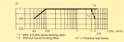
Telefunken S 4001 modulation capability
Linear distortion (frequency response)

The frequency response measured at any input voltage within the previously stated modulation capability of the transmitters deviates from the frequency response measured at m = 0.5 by not more than ±0.5 dB
Telefunken S 4001 linear distortion
Non-linear distortions (in broadcasting band: distortion factor) k equal or less than 3% at m = 0.8 from 40 Hz to AF bandwidth/2
Distortion frequencies above AF bandwidth/2 are measured as out-of-band emissions acc. to CCIR 328-5 (AM operating mode)
Spurious modulation - Signal-to-noise ratio More than 55 dB unweighted
More than 65 dB weighted acc. to DIN/IEC 244
ADDITONAL OPERATING MODES
DAM: Carrier amplitude vs. input modulation (idealized curve)

Residual carrier reduction and carrier offset are adjustable

Recommended residual carrier: 0.6
Recommended carrier offset: approx. 0.2
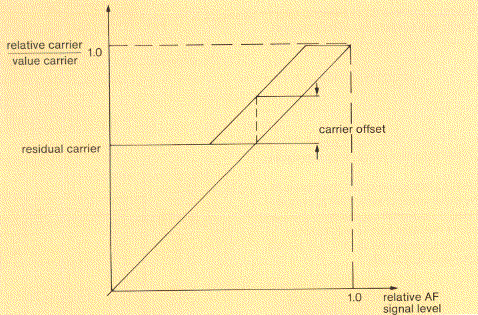
Telefunken S 4001 DAM
SSB broadcasting
Peak power
Transmitted sideband

Carrier reduction

Tolerance of carrier power
RF frequency change
RF power reduction

500 kW PEP
Upper sideband
(sideband change manual on drive unit or remote on control console)
-6 dB, -12 dB
(on request 2 additional carrier reduction values can be selected)
-10% to +15%
Full automatic tuning in the broadcast bands within 60 seconds
Manually adjustable to -3 dB
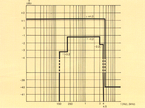
Linear distortion (frequency response) Telefunken S 4001 DAM
Non-linear crosstalk Intermodulation products -30 dB related to one tone at full modulation u = 100% (typical value -33 dB)
TRANSMITTER POWER SUPPLY
Mains supply 3-phase, 50 Hz up to 36 kV
Please state mains data when ordering
60 Hz version available on request
Rated load 1500 kVA
Total efficiency
typical ratings at m = 0.35
up to 21.8 MHz
21.8-26.1 MHz


68%
65%
Depending on operating frequency and spread between components, e.g. tubes, variations up to ±5% may occur
Power factor
Ratio of phase currents at rated load
More than 0.9
Less than 1.1
Specifications may change without notice

TUBE COMPLEMENT
RF stages AF stages and modulator
Number Type Number Type
1 TH558 1 TH558
1 TH561


THIS TYPE OF TRANSMITTER IS INSTALLED IN THE FOLLOWING COUNTRIES

ITU Country
ITU Country
flag AUT AUT AUSTRIA flag D D GERMANY
flag IRN IRN IRAN flag ISR ISR ISRAEL
flag J J JAPAN flag HOL HOL NETHERLANDS
flag NOR NOR NORWAY flag POR POR PORTUGAL
flag G G UNITED KINGDOM flag USA USA USA
flag CVA CVA VATICAN CITY