 | SHORTWAVE RADIO BROADCAST TRANSMITTERS |
 | SHORTWAVE RADIO BROADCAST TRANSMITTERS |
| GENERAL DESCRIPTION |
 RF Section
| TECHNICAL SPECIFICATIONS | |
| RF AND AF AMPLIFIERS | |
| Rated power | 300 kW carrier power ±8% with automatic tuning |
| Frequency range | 3.9 MHz to 26.1 MHz (broadcasting bands) (some frequencies outside the broadcast bands are available on request) |
| Frequency change | Fully automatic tuning within the broadcast bands Tuning time 30 seconds max. for AM, AM/reduced RF output power and DAM operation Tuning time 60 seconds max. for SSB |
| Operating modes | AM AM/reduced RF output (on request) DAM (on request) SSB (on request) |
| RF input - Input impedance - Standing-wave ratio - Driving power required RF output - Terminating impedance and max. standing-wave ratio - Rigid coaxial transmission line |
Z = 50 ohms VSWR equal or less than 2:1 at rated power 20 mW with permissible tolerance of ±3 dB Z = 50 ohms, VSWR equal or less than 2:1 at rated power (2 lt; vswr lt; 3):1 with automatic reduction of carrier power 66/152 (IEC 50-155) |
| Spurious emissions | Equal or less than 50 mW, i.e. equal or more than 68 dB attenuation related to carrier level |
| Out-of-band emissions | In compliance with CCIR 328-5 (measurement method with weighted noise) |
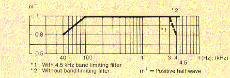
| Modulation - AF frequency range - AF input impedance - AF input level - Method of modulation |
40 Hz to 4500 Hz or 40 Hz to 7500 Hz (on request) other ranges on request 600 ohms or more than 2000 ohms balanced and ungrounded -4 dBm to +10 dBm for m = 1 and fAF = 1000 Hz, adjustable in 0.5 dB ubcrenebts Special AF processing on request Anode voltage modulation of final stage of RF amplifier by PDM amplifier (PANTEL) Co-modulation of screen grid of RF final stage tube via AF choke |
| Carrier and amplitude drop | Equal or less than 3% at m = 1 and fAF = 1000 Hz and constant mains voltage related to carrier voltage at m = 0 (AM operating mode) |
| Modulation capability during program operation | Any type of program modulatin up to a mean modulation factor of m = 0.75 permissible in continuous operation |
| Overmodulation | Overmodulation up to 10 dB are reduced to permissible values in the built-in limiter amplifier |
| Modulation capability in test operation (transmitter terminated by dummy load) One hour within a 6 hour period or 10 minutes within a 60 minute period |
 |
| Linear distortion (frequency response) The frequency response measured at any input voltage within the previously stated modulation capability of the transmitters deviates from the frequency response measured at m = 0.5 by not more than ±0.5 dB |
 |
| Non-linear distortions (in broadcasting band: distortion factor) | k equal or less than 3% at m = 0.8 from 40 Hz to AF bandwidth/2 Distortion frequencies above AF bandwidth/2 are measured as out-of-band emissions acc. to CCIR 328-5 (AM operating mode) |
| Spurious modulation - Signal-to-noise ratio | More than 55 dB unweighted More than 65 dB weighted acc. to DIN/IEC 244 |
| ADDITONAL OPERATING MODES | |
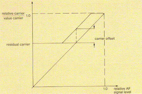
| DAM: Carrier amplitude vs. input modulation (idealized curve) Residual carrier reduction and carrier offset are adjustable Recommended residual carrier: 0.6 Recommended carrier offset: approx. 0.2 |
 |
| SSB broadcasting Peak power Transmitted sideband Carrier reduction Tolerance of carrier power RF frequency change RF power reduction |
300 kW PEP Upper sideband (sideband change manual on drive unit or remote on control console) -6 dB, -12 dB (on request 2 additional carrier reduction values can be selected) -10% to +15% Full automatic tuning in the broadcast bands within 60 seconds Manually adjustable to -3 dB |
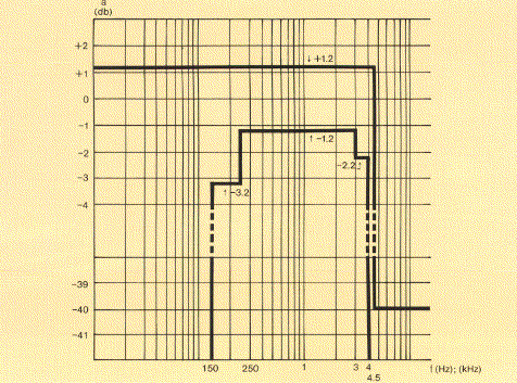
| Linear distortion (frequency response) |  |
| Non-linear crosstalk | Intermodulation products -30 dB related to one tone at full modulation u = 100% (typical value -33 dB) |
| TRANSMITTER POWER SUPPLY | |
| Mains supply | 3-phase, 50 Hz up to 36 kV Please state mains data when ordering 60 Hz version available on request |
| Rated load | 950 kVA |
| Total efficiency typical ratings at m = 0.35 up to 21.8 MHz 21.8-26.1 MHz |
67% 64% Depending on operating frequency and spread between components, e.g. tubes, variations up to ±5% may occur |
| Power factor Ratio of phase currents at rated load |
More than 0.9 Less than 1.1 |
| Specifications may change without notice | |
| TUBE COMPLEMENT | |||
| RF stages | AF stages and modulator | ||
| Number | Type | Number | Type |
| 1 | TH573 | 1 | TH573 |
| 1 | TH561 | ||
| THIS TYPE OF TRANSMITTER IS INSTALLED IN THE FOLLOWING COUNTRIES | |||||
| ITU | Country | ITU | Country | ||
| CLN | SRI LANKA | ||||