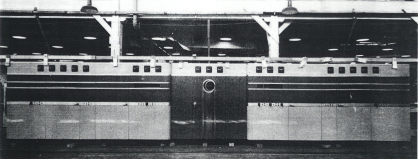
RCA MI-7330

GENERAL DESCRIPTION


50 KW SHORT WAVE BROADCAST TRANSMITTER

photo RCA MI-7330 The Short Wave Broadcast Transmitter described herein embodies a number of new developments from the RCA Laboratories which combine to produce an efficient and economical high power equipment for broadcasting in the International Short Wave Bands. Among these developments are new type high-frequency power tubes, simplified automatic control circuits, all a-c operation, new designs of high power audio frequency transformers, and new high~frequency tank circuit designs.

The transmitter is designed with two separate r-f channels, each capable of operating at any chosen frequency in the range from 6 to 22 megacycles. Rapid change can be made between any two frequencies by changing r-f channels, and any third frequency can be set-up on either channel while the other is in operation. Each r-f channel is provided with its own output terminals, which may be connected directly to an antenna transmission line, or to a transmission line switching system external to the transmitter.

High level Class B plate modulation of the output r-f amplifier is used because of its high overall efficiency. In this system the power required is reduced for average program modulation, increasing momentarily at a syllabic rate on modulation peaks. The output r-f amplifier employs two tubes, in a push-pull circuit. The modulator also uses two tubes, and is excited by a series of low power push-pull Class A audio stages. New methods of transformer and circuit design and the use of stabilized feed-back in the audio system give outstanding quality of modulation.

The control system has been designed to provide full automatic operation with greatly simplified circuits, using rugged, reliable components. Improved overall transmitter efficiency results in lower power consumption, also smaller power supply units and smaller cooling system equipment. With all a-c operation, motor-generator sets and rotating power apparatus have been eliminated. Power transformers may be located out-of-doors if desired, and, while, a two floor building is recommended for convenience in making piping and high voltage connections, a single floor layout can also be used readily. High reactance type filament transformers are empIoyed, eliminating the need for complicated starting resistor control on the filament circuits of the larger tubes.

The cooling system is of the closed type, using distilled water, and includes a storage tank, regular and spare circulating pumps and surface type cooler. The distilled water system is made up entirely of nonferrous metals and porcelain, and contains no organic materials which might contaminate the water and lower its insulation resistance.

The power amplifier uses two tubes connected push-pull in a high efficiency Class C circuit. Amplitude modulation of the carrier is accomplished in the plate circuit by the Heising system, using a high efficiency, Class B modulator. The modulator is driven by a chain of three audio amplifiers in cascade, the last amplifier exciting the modulator tubes through a "cathode-follower" circuit which results in smaller components and simplified amplifier design. The modulation system employs the latest exclusive RCA technique in determining the constants of the transformer, reactor and capacitors, to obtain optimum performance with smaller and less costly equipment.

In the mechanical design of the equipment great care has been taken to use rugged components and to arrange the various parts to facilitate operation and maintenance of plant. The disposition of the equipment and the arrangement of the enclosure and partitions allow observation of the various units in operation while at the same time reducing operating hazards to personnel to a minimum. With maximum convenience, the Transmitter Enclosure also presents an attractive modern appearance, leading the field in functional industrial styling.

All transmitter tubes except the final r-f amplifiers and the modulators are air-cooled. These latter are water-cooled, using a closed distilled water system, designed to reduce water losses to a minimum. Regular and spare circulating pumps are both connected to provide immediate change-over in case of necessity.

Individual instruments are provided in all important tube circuits to permit accurate observation of the performance of all parts of the equipment. Instruments connected with power supply, rectifier voltages, and the final r-f amplifier and modulator tubes are mounted at appropriate points on the front enclosure. Instruments for the r-f exciter, as well as tuning controls, are located inside the enclosure door in front of each r-f channel. An inner door is interlocked, so that no high voltage circuits are exposed when checking or adjusting the transmitter.

Several functions are combined in the control circuits, including safety to personnel, protection of equipment, complete automatic or manual control of operation, and automatic change from one r-f channel to the other. In respect to protection of personnel, the electrical door interlocks are so connected as to remove all dangerous voltages and ground all d-c circuits when the doors giving access to the transmitter are opened. The interlock circuits are so arranged that power is required to maintain operation. A failure of control circuit power or a break in the interlock or grounding relay circuits will result in shut down.

Protection to equipment is provided for by time delay relays which prevent application of bias or plate voltage to rectifiers or power tubes until the filaments have been properly heated, also by high speed overload protection, by means of individual relays in the plate circuit return of power tubes and in the primary feed circuits to rectifier plate supply transformers.

Individual control switches are provided so that the various filament, bias and plate circuits may be turned on and off separately during tests or "trouble shooting". These switches are located in groups at appropriate places on the transmitter enclosure. If these control switches are placed in the "on" position in advance, then the transmitter can be put into full operation by throwing the station start switch, which will turn on filaments and, after necessary delay, the bias and plate supplies. Provision is also made for either automatic reclosure or lockout operation. In the latter case, an overload will result in shutting off of plate circuit power. In the former case, the plate power will be reapplied automatically after an overload, unless three overloads occur in rapid succession, in which case shut down will result.

The transfer feature is controlled by a time sequence relay which, when the "transfer" control is operated, will remove plate voltages, automatically operate the necessary power supply transfer contactors, and then reapply plate voltages.

The console is provided with indicator lamps for all important circuits, also with switches for shutting down the high voltage supplies in case of emergency. It is also provided with a volume indicator and various switches and gain controls for handling incoming programs to the transmitter.

The whole equipment is designed in conformity with the most up- to-date practices of good engineering, and will conform to standards of the American Institute of Electrical Engineers and of the United States Federal Communications Commission.

TECHNICAL SPECIFICATIONS
Type of Emission A3 - Telephone
Power Output (300 to 600 ohm balanced line) 50 KW
Frequency Range 6 to 22 MC
Frequency Stability 10 parts per million guaranteed
Power Supply Requirements 2300 volts, 50 cycle, 3 phase. Regulation, from no load to full transmitter load, not to exceed 5% of total.
Voltage variation due to regulation and other causes should not exceed 10% of nominal 2300 volts.
Average program requirements 120 KW - Power Source should be capable of supplying 200 KW.
A separate 115 volt, 50 cycle supply for the crystal heaters is required.
Power Input:
Average program level
Modulation Factor = 1

Approximately 120 kW
Approximately 150 KW
Type of Modulation High level class "B"
Audio Frequency Input 600 ohms:
Average program level
Modulation factor = 1.0
Audio Frequency Response

0 VU
approx. 6 VU
Uniform within ±1.5 DB, 30 to 10,000 cycles
Audio Frequency Distortion
Residual Noise
Envelope Distortion
60 db below 100% modulation
4% r-m-s at 1000 cycles and 90% modulation
Specifications may change without notice

TUBE COMPLEMENT
RF stages AF stages and modulator Rectifiers
Number Type Number Type Number Type
4 802 2 1603 6 857B
4 828 8 828 6 872A
4 810 2 880

4 827R 2 836

4 880 2 872A


THIS TYPE OF TRANSMITTER IS INSTALLED IN THE FOLLOWING COUNTRIES

ITU Country
ITU Country
flag AUS AUS AUSTRALIA flag CAN CAN CANADA
flag MRC MRC MOROCCO flag G G UNITED KINGDOM