| GENERAL DESCRIPTION |
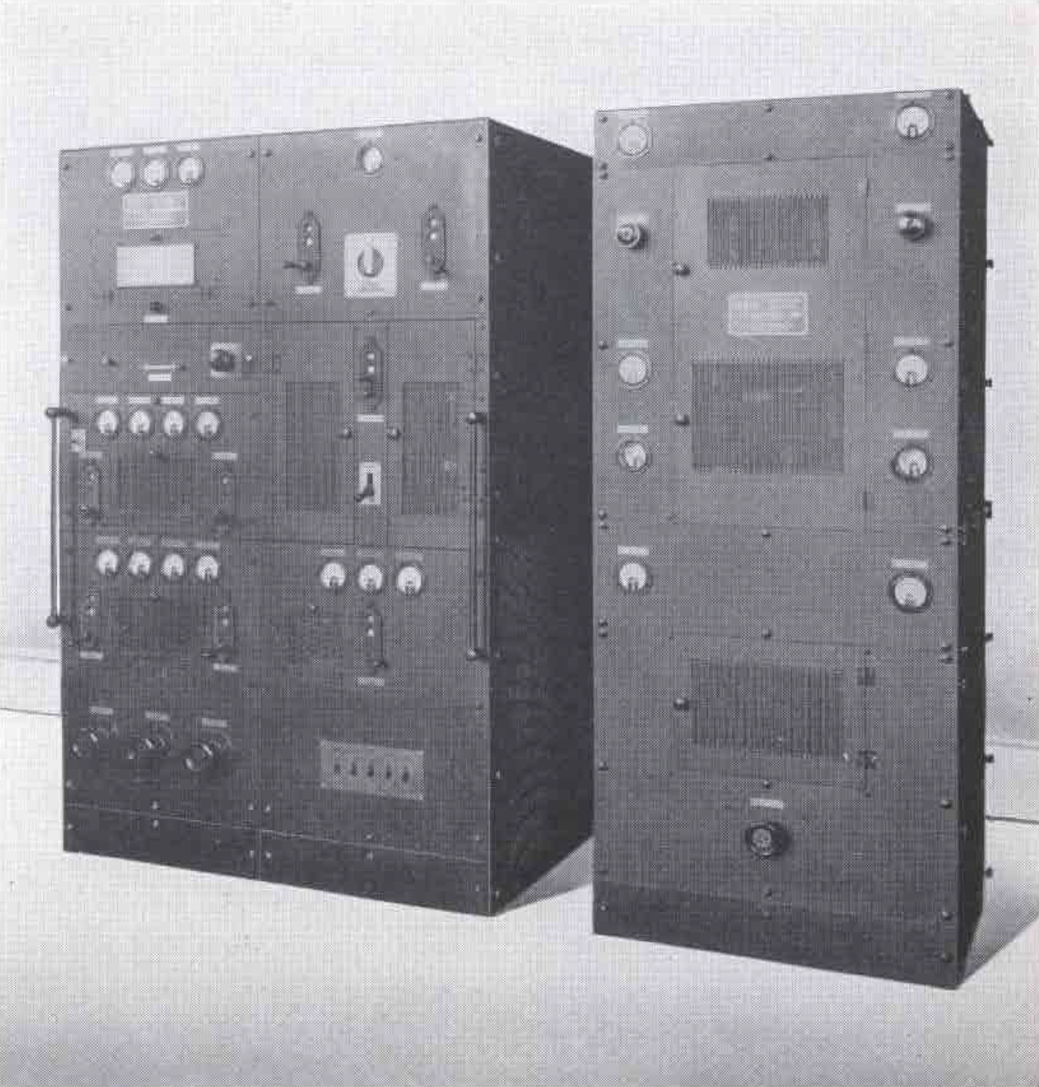 Sociologists have an intensive interest in international broadcasting because of the effect such wide intercourse will have in bringing together the diverse races of the earth. Students of economics, history, and language are similarly intrigued by its possibilities. But their interests are purely acedemic-concern only distant and indirect results. Broadcasters have a more immediate and tangible interest - the commercial application of international broadcasting. True, the presently available channels are restricted to experimental use - but this may not always be the case. Many manufacturers are building thousands of short-wave adapters as well as combination sets. The army of short-wave listeners being formed may soon start demanding more and better programs - something that can only be furnished by a service which is self-sustaining. The networks and several of the larger independent stations are preparing for this by operating short-wave relay stations on regular schedules. Unfortunately, the operation of a short-wave auxiliary is, for most stations, not yet economically justifiable. Nevertheless all broadcast stations are anxiously interested in the future of short-wave broadcasting and hence most readers of BROADCAST NEWS will be much interested in the new transmitter which engineers of the RCA Victor Company, Inc. have designed for W2XE, Columbia Short-Wave Relay station.
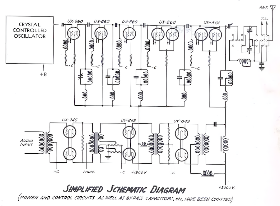
| TUBE COMPLEMENT | |||||
| RF stages | AF stages and modulator | Rectifiers | |||
| Number | Type | Number | Type | Number | Type |
| 2 | UV-861 | 2 | UV-849 | ||
| 5 | UV-860 | 2 | UV-845 | ||
| 2 | UX-245 | ||||
| THIS TYPE OF TRANSMITTER IS INSTALLED IN THE FOLLOWING COUNTRIES | |||||
| ITU | Country | ITU | Country | ||
| BOL | BOLIVIA | USA | USA | ||