PHILIPS SOZ 363

GENERAL DESCRIPTION


photo Philips SOZ 363 
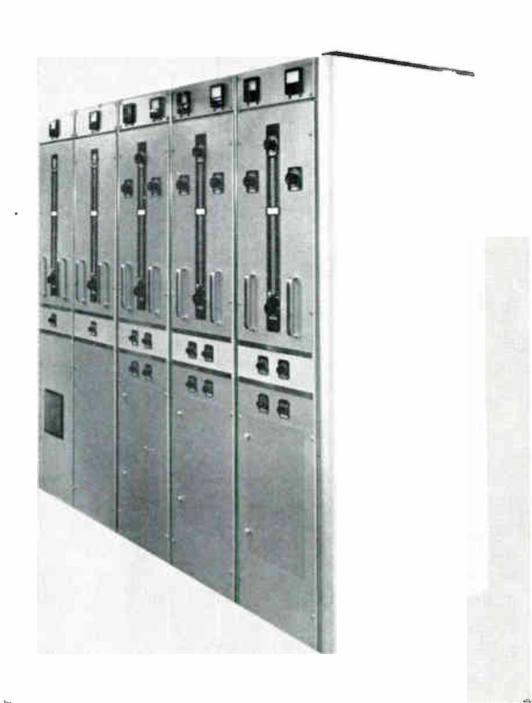
10 kW AM SHORT-WAVE TRANSMITTER TYPE SOZ 363 channelized

General

This air-cooled transmitter embodies a number of properties which render it particularly suitable for use in broadcast stations where nonspecialized staff are employed.

The transmitter is easily installed without special tools or special knowledge. Because it consists of individual units, full advantage can be taken of the available space. The transmitter is easy to control and tune and is suitable for unattended operation. Facilities for remote control are included.

Maintenance requires no special training, while doors and slide-out panels give easy access to all components. Extensive precautions throughout the transmitter protect it from damage by faulty switching manipulations, and the operating staff from dangerously high voltages.

Description

The transmitter consists of a number of individual units, viz, a modulator unit, a power supply unit, up to 5 RF units and a few large component parts, such as transformers and ventilating fans.

Each of the RF units can be pre-set to a specific frequency in the 2.2-28 Mc/s band and is supplied with tuning elements for that frequency. In this way, a change-over from one RF unit to another can be made within one second, thus permitting a rapid change in frequency.

Aerials may be switched over automatically at the same time by means of a built-in aerial relay. These provisions render it possible to make a highly efficient use of the transmitter.

The transmitter satisfies international standards. It has been used in many countries all over the world for years and has always given complete satisfaction. Frequency stability is enhanced by a crystal-controlled exciter unit. This unit is also suitable for self-oscillation in case of emergency. The use of an external oscillator is also possible.

The modulator consists of push-pull circuits through-out and, because of its special feedback circuit, excellent sound reproduction is ensured.

Mechanical design

The modulator, power supply and RF units are housed in individual all-metal cabinets of pleasing design. The controls and meters are conveniently arranged. The modulator and RF units are fitted on slide-out panels.

The large components, such as the modulation and high-tension transformers, may be set up behind the transmitter proper or installed in a separate room (e.g. a cellar).

The ventilating fans for the air-cooling of the transmitter may be arranged in various ways, so that the cooling system can be adapted to local circumstances. The carefully selected components make the transmitter suitable for use in tropical climates. A detailed assembly and maintenance manual is supplied with the transmitter. Like the inscriptions on the latter, this manual is normally in English, but other languages (e.g. Spanish) are available on request. Also supplied are certain spares, such as pilot lamps and fuses, as well as some enamel for touching-up purposes.

TECHNICAL SPECIFICATIONS
Frequency range 2.2-28 Mc/s in 7 sub-ranges
Frequency tolerance ±20.10-6 (2.2-4 Mc/s);
±15.10-6 (4-28 Mc/s)
Power output 10 kW (carrier)
Output impedance 600 ohms balanced; 50 or 75 ohms unbalanced, on special request
Standing wave ratio max. 1.4:1
Spurious radiation according to CCIR recommendations
AF input impedance nominal 600 ohms balanced
AF input level 0 dBm ±2 dB, reference 1000 c/s at 100% modulation; 0 dBm = 1 mW into 600 ohms
Linear distortion within ±1.5 dB from 30-10,000 c/s, reference 1000 c/s at 60% modulation
Non-linear distortion less than 3% from 50-10,000 c/s at 90% modulation
Noise level better than -60 dB unweighted, reference 1000 c/s at 100% modulation
Modulation capability 100%
Power supply 3 x 380 V ±5%, 50 and 60 c/s ±5%, four-wire mains; adaptation to other voltages is possible by means of an optional separate autotransformer
Power consumption transmitter with 1 RF unit:
at 0% modulation approx. 21 kW
at 30% modulation approx. 24 kW
at 100% modulation approx. 30 kW
at stand-by 4 kW
Power consumption per additional RF unit:
at stand-by: approx. 1.7 kW
Power factor approx. 0.82
Ambient temperatures at sea level: +10° to +45° C under tropical conditions; at 6000 ft: +10° to +35° C
Relative humidity up to 95%
Dimensions (approx.) transmitter with 1 RF unit: height 212 cm (84 in.), width 152 cm (60 in.), depth 90 cm (36 in.)
Minimum floorspace 300 x 350 cm (120 x 140 in.)
Weight (approx.) transmitter with 1 RF unit: 2500 kg (5500 lb.) unpacked

TUBE COMPLEMENT
RF stages AF stages and modulator Rectifiers
Number Type Number Type Number Type
4 QBL5/3500 (6076) 4 QBL5/3500 (6076) 3 DCG6/18 (6693)
5 QQE06/40 (5894) 8 QE06/50 (807) 8 DCG4/1000G (866A)
1 OA2


1 E80L (6227)


1 EF91 (6AM6)


THIS TYPE OF TRANSMITTER IS INSTALLED IN THE FOLLOWING COUNTRIES

ITU Country
ITU Country
flag OMA OMA OMAN flag SUR SUR SURINAME