 I. Introduction
Recently, Philips Telecommunication Industries delivered to the "Stichting Radio Anno Santo" a short-wave broadcast transmitter which will, in the near future, be installed at Vatican Radio. The carrier output of this transmitter is 100 kW and the frequency range 5.6-26.1 Mc/s (λ = 52 - 11.5 m).
The transmitter has been built according to the latest developments and has been provided with an automatic tuning mechanism which allows adjustment within two minutes of the various tuning circuits to any one of six preset frequencies and selection of the corresponding correct voltages, by means of one single frequency-selector switch on the control desk. In addition, manual tuning or correction of tuning is possible without disarranging the preset positions of the instantuners. For automatic frequency selection the small type instantuner 1) is used for the first stages, while a large type 2) is applied in the penultimate and final stages. The large type of instantuner allows of manual correction of the tuning after the desired preset frequency has been selected. This may be necessary, for instance when the feeder impedance changes under the influence of varying weather conditions. However, after a subsequent selection of a preset frequency for which manual correction of one or more of the tuning elements was necessary, the original pre-set position of the tuning elements will be obtained.
The units of the transmitter, viz. preceding stages, final stage, modulator, power supply, distribution panel, high-voltage rectifier etc., are mounted in separate frames which are placed behind a "dead front" provided with doors. On the upper part of this front is a metering panel. The transmitter is controlled and supervised from the control desk which is placed in front of the transmitter. As a result of the simplicity of the manipulations, only a few minutes are required for changing over from one preset-frequency to another.
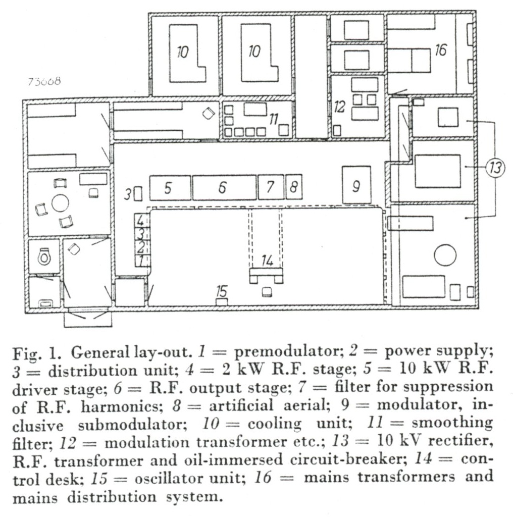 Since the transmitter consists of separate units, various arrangements are possible which allow a suitable lay-out for almost any kind of transmitter building. The standard arrangement is shown in fig. 1, while fig. 2 shows a model of the transmitter.
In the completed transmitter, the various frames form one screened unit so that interference due
to direct radiation has been reduced to a minimum.
Since the transmitter consists of separate units, various arrangements are possible which allow a suitable lay-out for almost any kind of transmitter building. The standard arrangement is shown in fig. 1, while fig. 2 shows a model of the transmitter.
In the completed transmitter, the various frames form one screened unit so that interference due
to direct radiation has been reduced to a minimum.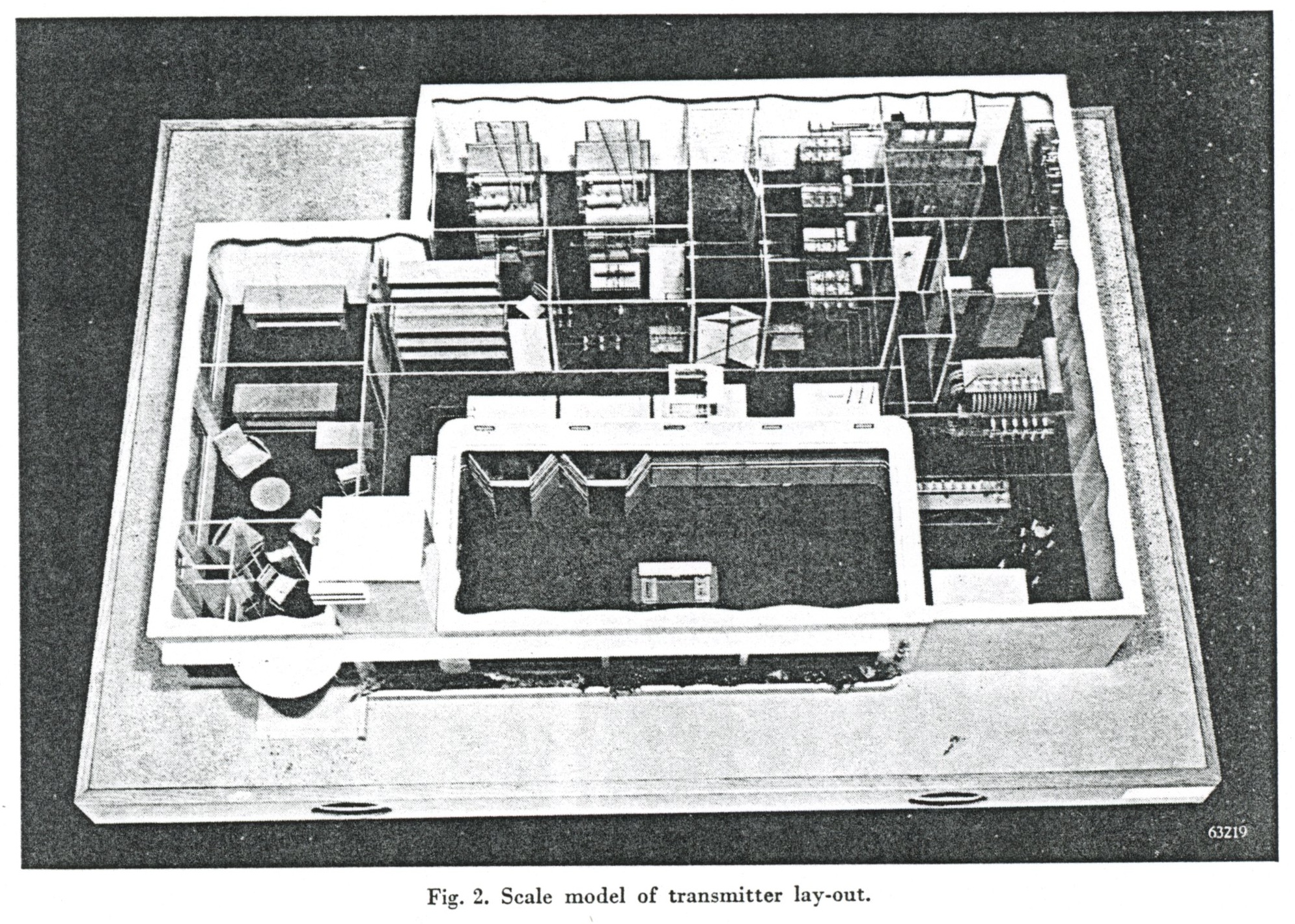 In order to obtain a pleasing appearance, the transmitter is placed behind a front panel provided
with doors. Access to the tuning knobs and the supervisory instruments can be obtained via doors.
In order to obtain a pleasing appearance, the transmitter is placed behind a front panel provided
with doors. Access to the tuning knobs and the supervisory instruments can be obtained via doors.The attending personnel is safeguarded by means of an interlocking system which meets the most stringent requirements. High voltages are automatically switched off when the door in front of the particular high-voltage unit is opened, and high-voltage charges on condensers are short-circuited by means of earthing switches.
Al d-c voltages up to 1000 volts are supplied by means of selenium rectifiers; the 3000 volts suply is obtained by means of a valve rectifier, and the 10 kV voltage for the modulator, the penultimate and the final H.F. stage is supplied by means of a mercury-steel rectifier.
When the water pipes for the cooling system, and the cables for the interconnection of the various units, are mounted in a cable duct, a cellar is not necessary.
The transmitter has been designed so that reliable operation is obtained under widely varying climatic conditions. Where necessary, components are heavily silver-plated.
A special oscillator is provided to obtain a very high degree of stability on each preset frequency.
Fig. 3 shows the block diagram to which the reader is referred in connection with the detailed description of the transmitter that will now be given.
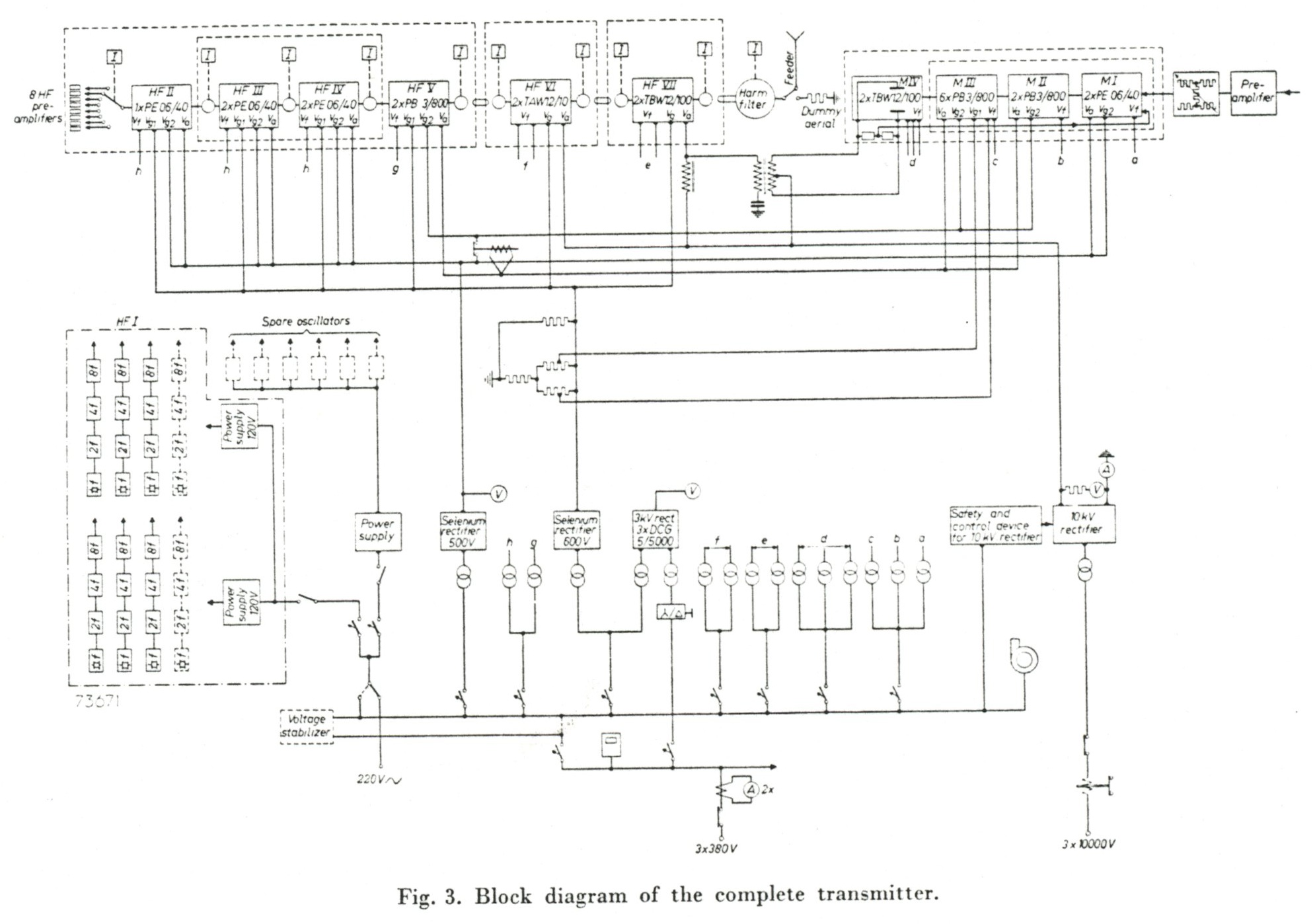
 For each of the six preset frequencies a separate exciter channel has been provided; in addition, two spare channels are available.
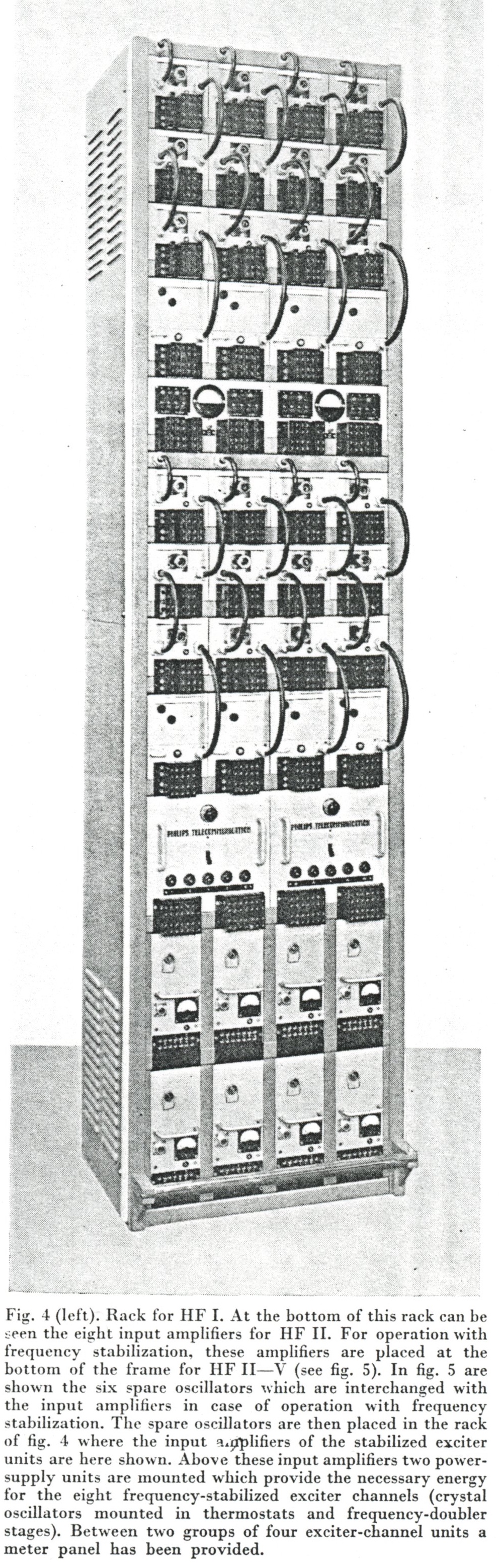
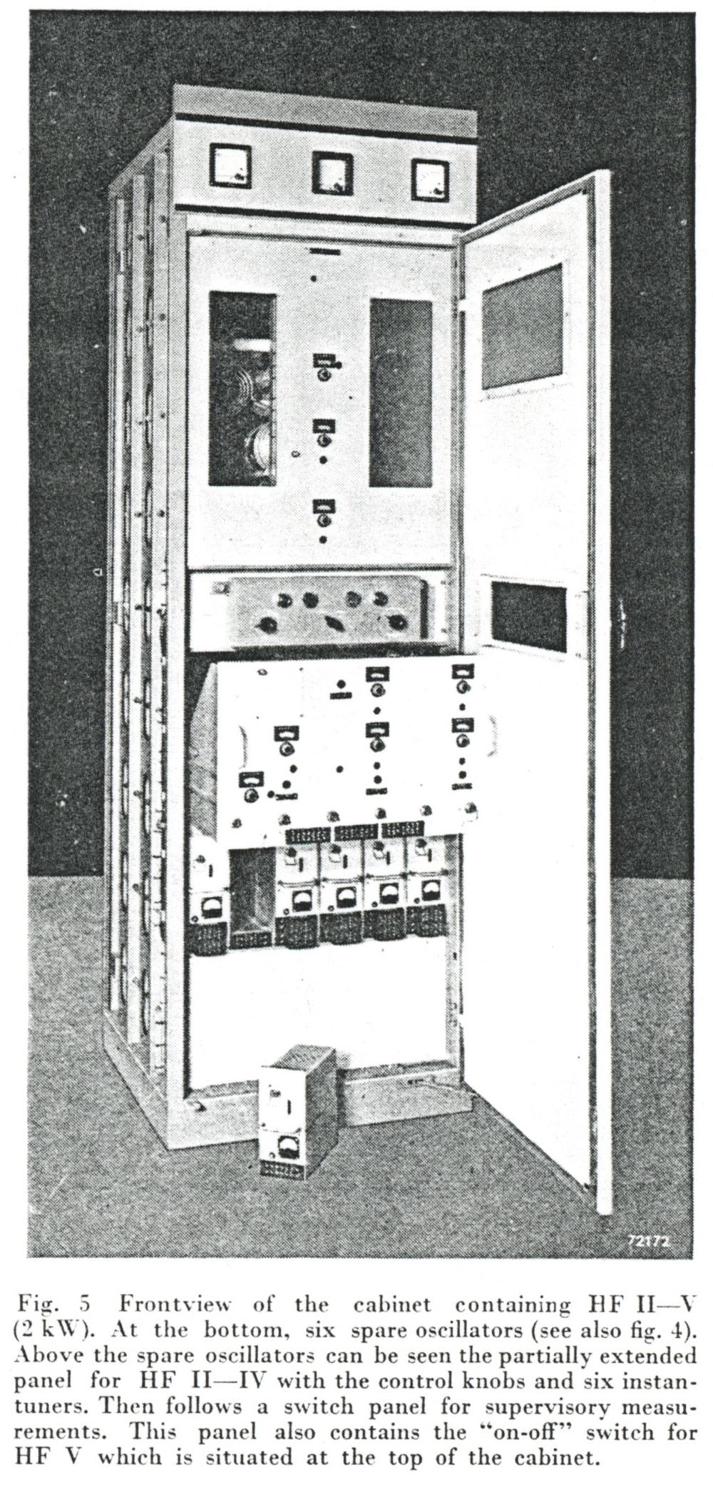 The eight exciter channels are mounted in one rack (HF1) which can be placed anywhere in the transmitter building. The common last stage of all exciters (the input amplifier of HF II) is not placed in this rack but in the cabinet for HF II-V. Each exciter channel consists of a crystal-sontrolled oscillator of special design, three frequency-doubler stages and the inut amplifier of HF II already mentioned.
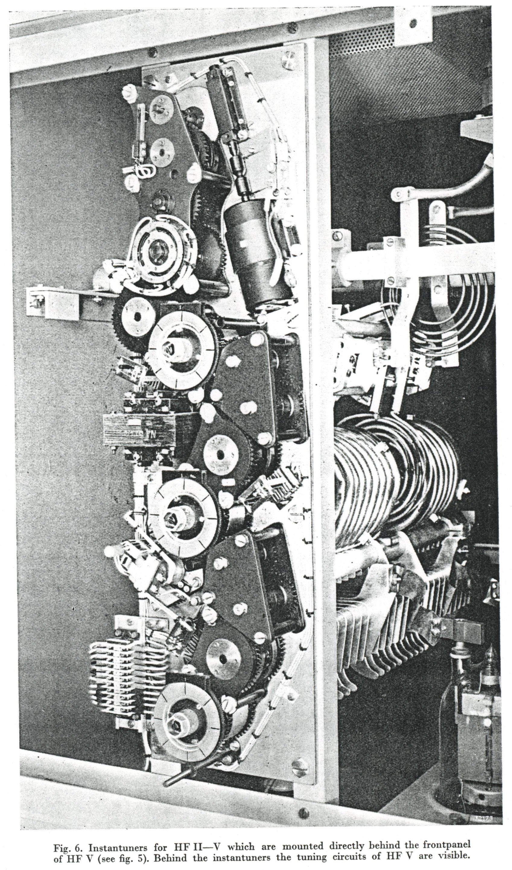 The rack HF I with the exciter channels is followed by a cabinet (fig. 5 and 7) in which the amplifier and frequency doubler stages HF II, III and IV are mounted. The frequency of the input signal lies between 2 and 7.2 Mc/s. HF II operates either as an amplifier or as a frequency doubler, whereas HF III always operates as a frequency doubler. HF IV and HF V are high-frequency push-pull amplifier stages and are both tuned to the ultimate operating frequency.
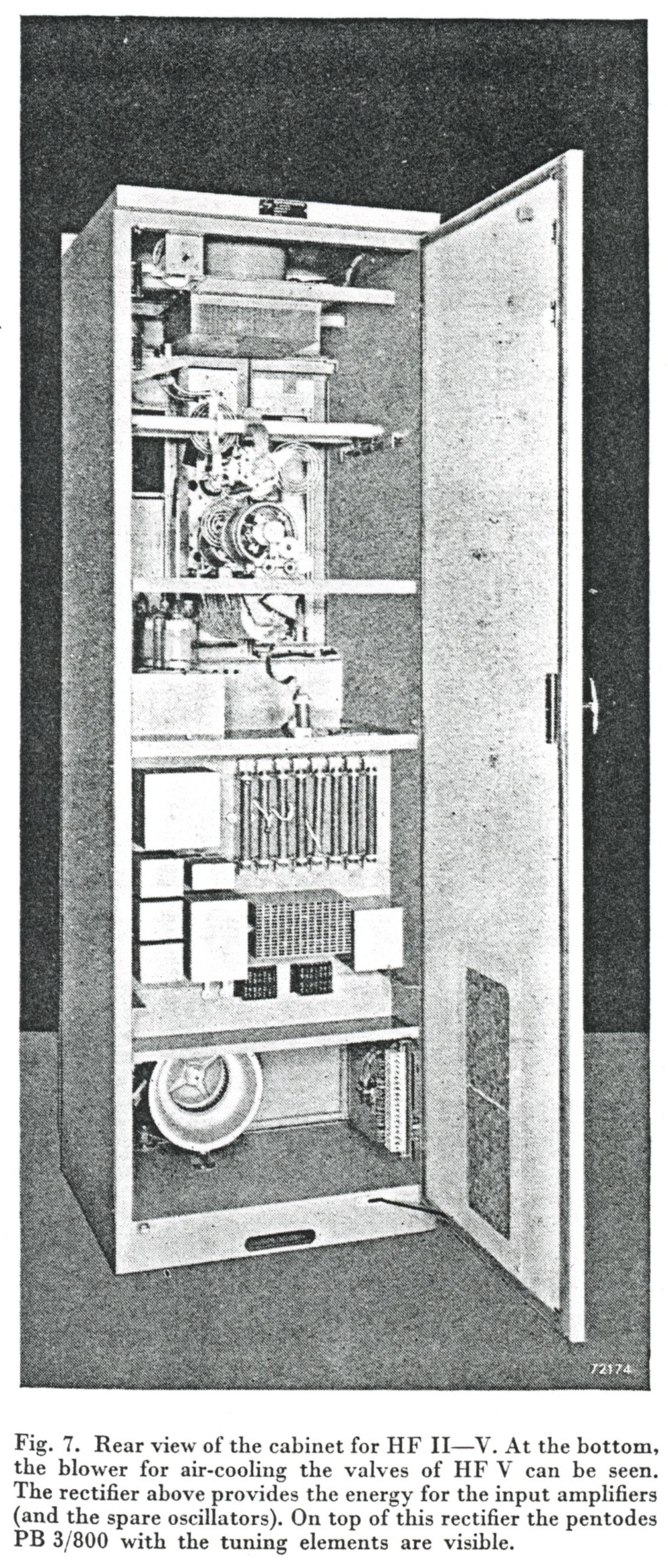 The six input amplifiers are placed in the lower part of the cabinet (fig. 5). The high-frequency stages HF II-V mounted together in one chassis which is supported by means of telescopic mountings. In fig. 5 this chassis is shown partially extended. The tuning elements of these stages and the frequency-selector switch which is mounted on this panel, are operated by instantuners.
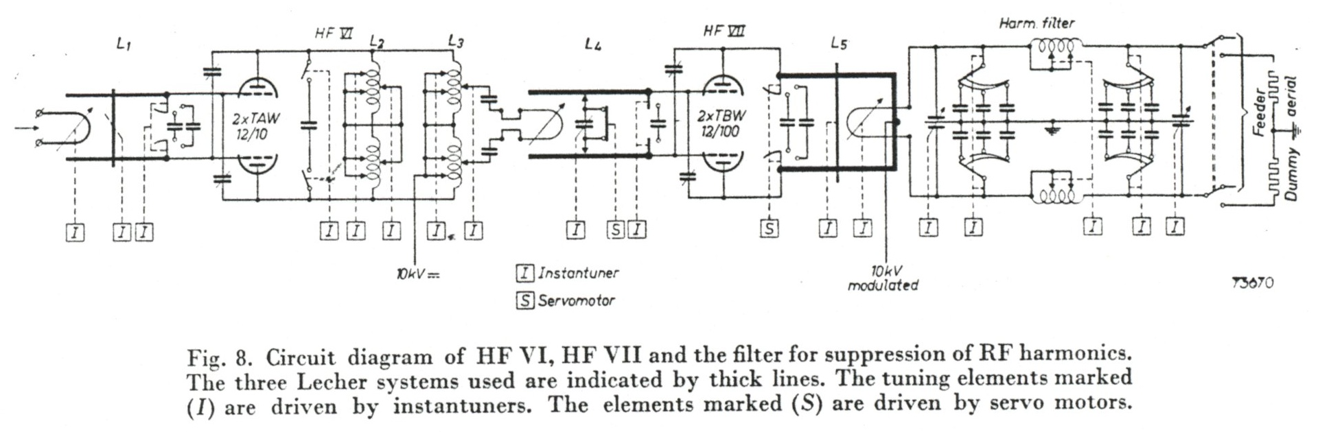 The output of the driver stage, which operates with two water-cooled triodes, type TAW 12/10,
in push-pull, is approx. 10 kW.
The output of the driver stage, which operates with two water-cooled triodes, type TAW 12/10,
in push-pull, is approx. 10 kW.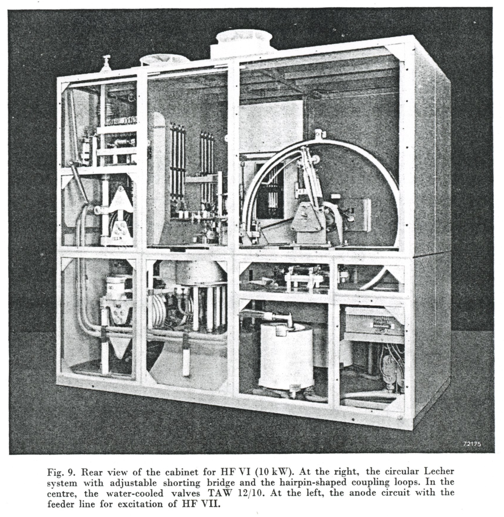 Fig. 9 gives a rear view of HF VI (covers removed); at the right, the folded Lecher system is visible.
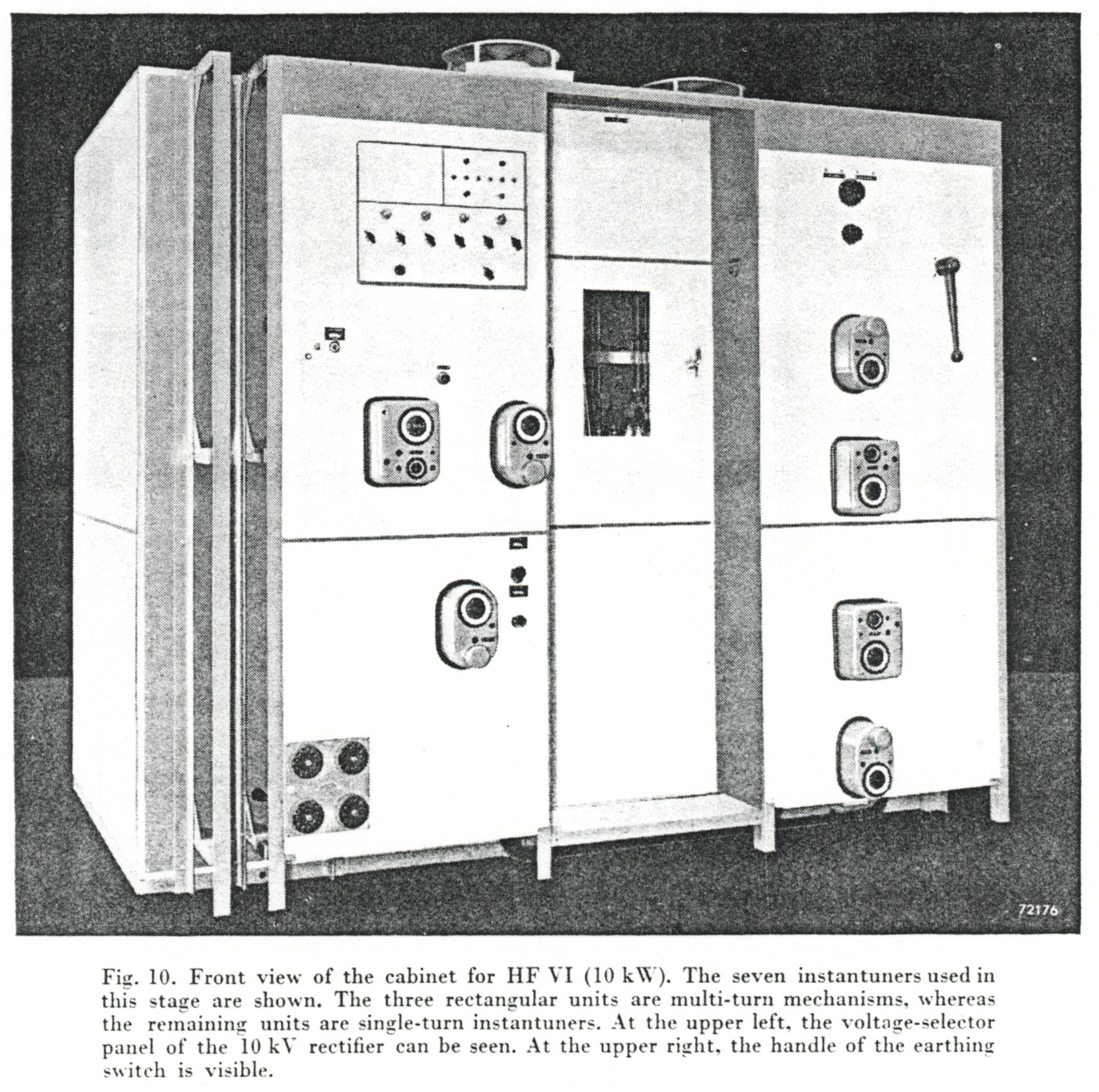 As in the 40 kW transmitter, triple contacts have been applied for tuning the Lecher system and for switching the various condensers 3). These triple contacts are fitted to two ceramic rods which rotate on a shaft mounted in the centre of the circular Lecher system. By rotating the shaft, a movable short-circuit is obtained. On this shaft can also be rotated the loop for the variable coupling with the preceding stage HF V. These tuning elements are driven by means of the respective instantuners which are mounted at the front of the particular cabinet section. The control units of these instantuners can be seen in fig. 10.
At the upper left (fig. 10) are mounted the switches for selecting the high voltage corresponding with
the various operating frequencies, selection of the correct high voltage being necessary in order to
ensure correct operation of the valves in the output stage. At the right, the instantuner for tuning
the anode circuit can be seen.
As in the 40 kW transmitter, triple contacts have been applied for tuning the Lecher system and for switching the various condensers 3). These triple contacts are fitted to two ceramic rods which rotate on a shaft mounted in the centre of the circular Lecher system. By rotating the shaft, a movable short-circuit is obtained. On this shaft can also be rotated the loop for the variable coupling with the preceding stage HF V. These tuning elements are driven by means of the respective instantuners which are mounted at the front of the particular cabinet section. The control units of these instantuners can be seen in fig. 10.
At the upper left (fig. 10) are mounted the switches for selecting the high voltage corresponding with
the various operating frequencies, selection of the correct high voltage being necessary in order to
ensure correct operation of the valves in the output stage. At the right, the instantuner for tuning
the anode circuit can be seen.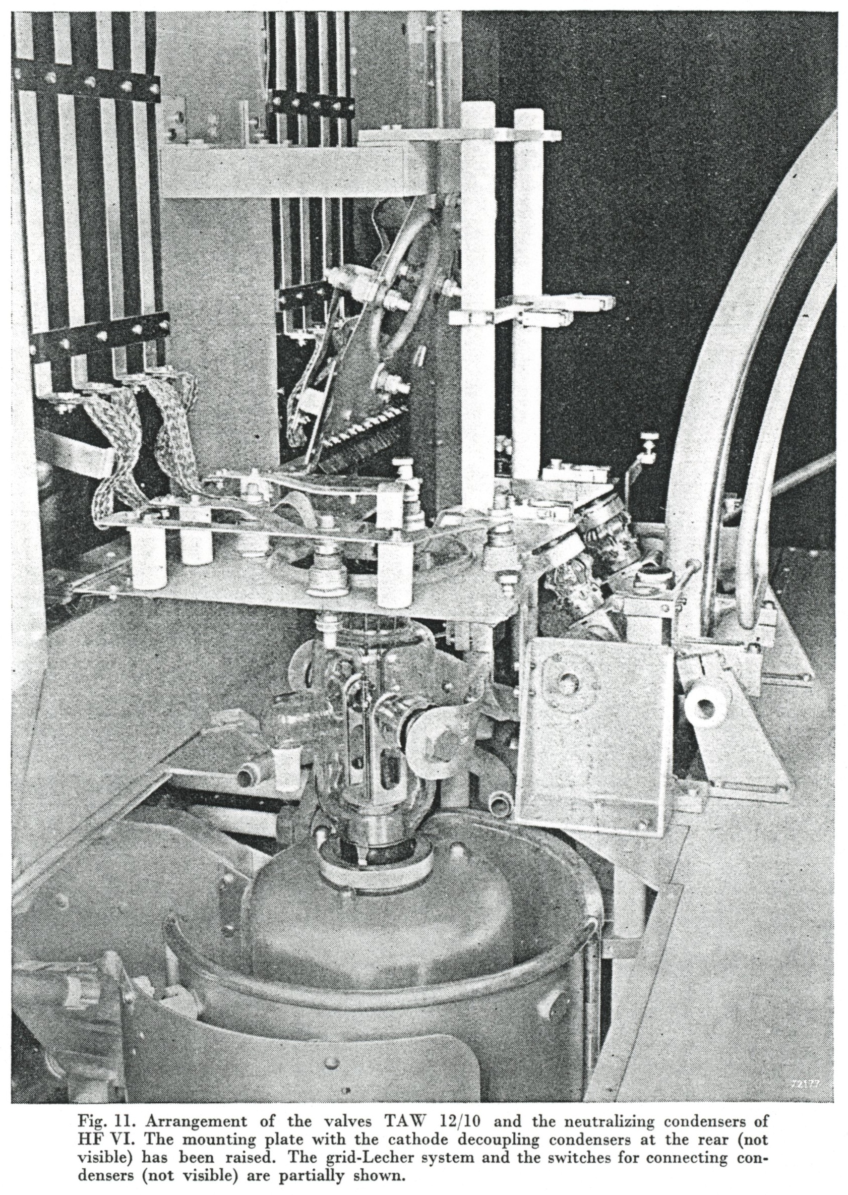 The neutralizing condenser is formed by the jacket of the valve holder which has the same potential as the anode of the valve, and by a cylindrical jacket which has been placed concentrically with respect to the jacket of the valve holder. Part of this outer jacket is hinged; by varying the position of this part the neutralizing capacity can be varied. The outer electrodes of the neutralizing condensers are connected to the grids of the valves in a special way by means of straps.
As a result of a balanced construction, both electrically and mechanically, of the jacket of the neutralizing condenser, it is possible to maintain one position of the hinged section throughout the frequency range of 5.6 Mc/s to 26.1 Mc/s. Fig. 11 shows the neutralizing condenser and, in addition, the gland nut with which the valve is fastened to the cooler. The method used for fastening the valves to the coolers allows for rapid replacement.
To improve the accessibility, the horizontal mounting plate with various decoupling condensers can be turned upwards. In fig. 11 (at the left) a raised mounting plate can be seen behind the valve. The same figure also shows the switch contacts for connecting the fixed condensers across the Lecher system (the condensers are not visible in the figure).
The neutralizing condenser is formed by the jacket of the valve holder which has the same potential as the anode of the valve, and by a cylindrical jacket which has been placed concentrically with respect to the jacket of the valve holder. Part of this outer jacket is hinged; by varying the position of this part the neutralizing capacity can be varied. The outer electrodes of the neutralizing condensers are connected to the grids of the valves in a special way by means of straps.
As a result of a balanced construction, both electrically and mechanically, of the jacket of the neutralizing condenser, it is possible to maintain one position of the hinged section throughout the frequency range of 5.6 Mc/s to 26.1 Mc/s. Fig. 11 shows the neutralizing condenser and, in addition, the gland nut with which the valve is fastened to the cooler. The method used for fastening the valves to the coolers allows for rapid replacement.
To improve the accessibility, the horizontal mounting plate with various decoupling condensers can be turned upwards. In fig. 11 (at the left) a raised mounting plate can be seen behind the valve. The same figure also shows the switch contacts for connecting the fixed condensers across the Lecher system (the condensers are not visible in the figure). The output stage is built in two separate cabinets. The frame adjoining the 10 kW stage contains a similar Lecher system (L4, fig. 12) to that in the preceding stáge (fig. 8). As a result of the large input capacity of the 100 kW transmitting valves which are mounted in this frame, this grid circuit has also been designed for three frequency ranges. This is obtained by electrically shorting or extending the Lecher bars. For the middle frequency range the ends of the Lecher bars are short-circuited by means of a movable short-circuiting bridge. For the upper frequency range the short-circuiting bridge is replaced by fixed condensers which, for the two lower frequency ranges, are shorted by means of contacts driven by a servo-motor. The lowest frequency range is obtained by connecting fixed condensers between the grids of the transmitting valves. Except for the servo-mechanism the construction of this grid circuit is the same as that of the 10 kW stage.
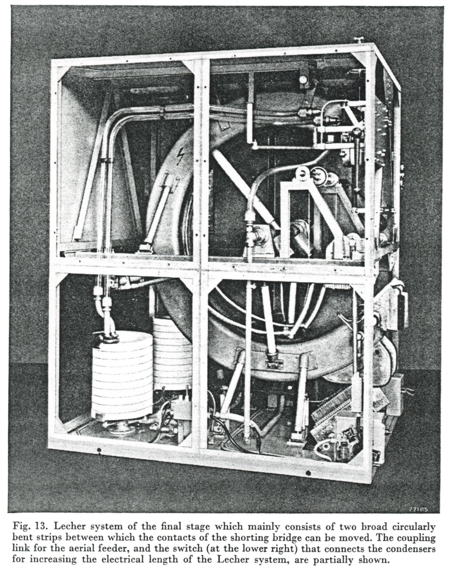
 The anode circuit of the final stage is mounted in a separate frame placed adjacent to the preceding frame (fig. 13). For the anode-circuit tuning, use has also been made of a Lecher system (L5 of fig. 7), the length of which can be varied by means of a short-circuiting bridge. Here too, the electrical length of the Lecher system can be extended by switching fixed condensers into the circuit.
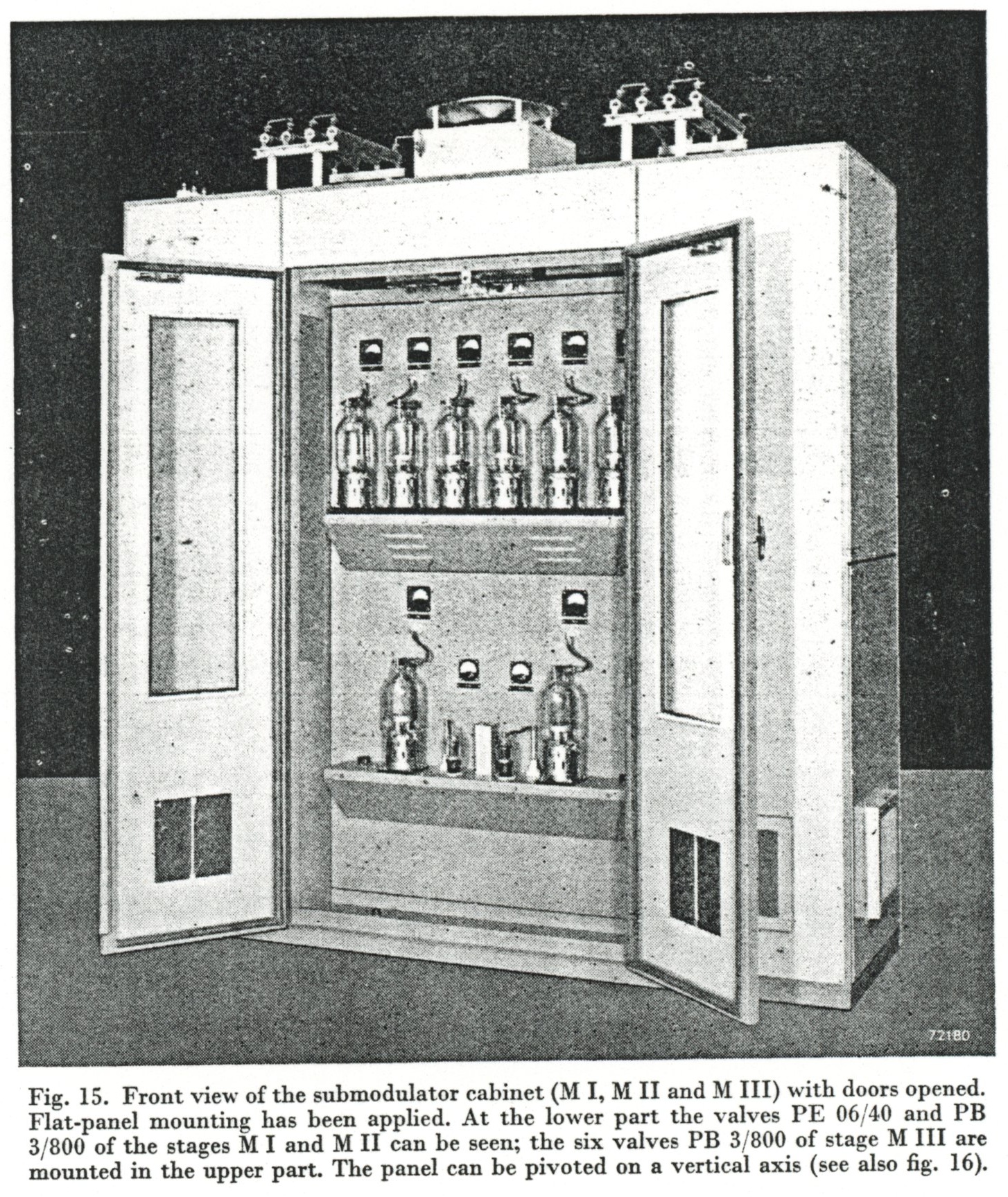
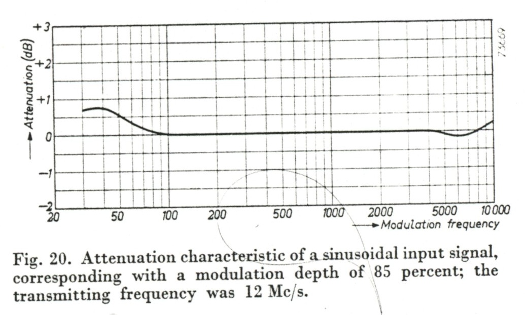
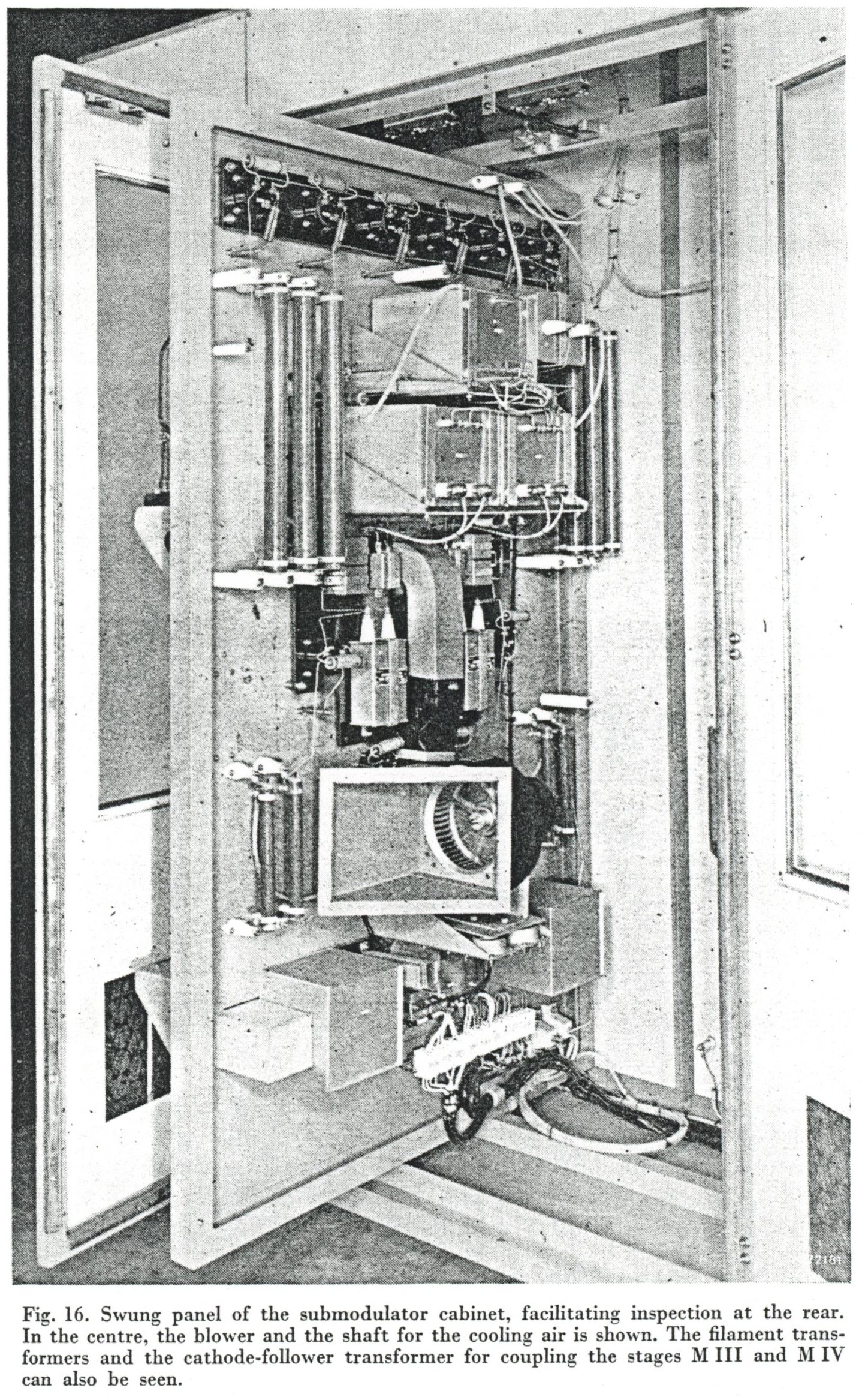 The energy for modulating the high-frequency output stage is supplied by an AF amplifier, the final stage of which operates with the same type of valves (viz. TBW 12/100) as are used in the high-frequency output stage. In fig. 3, a block diagram of the AF amplifier is given, showing that the AF signal is fed to the submodulator via an H-attenuator mounted on the control desk. By means of various AF stages this signal is amplified up to the required level. For a modulation depth of 100 percent the input-signal voltage must be adjusted to 1.5 volts RMS across a characteristic impedance of 600 ohms, by means of the H-attenuator.
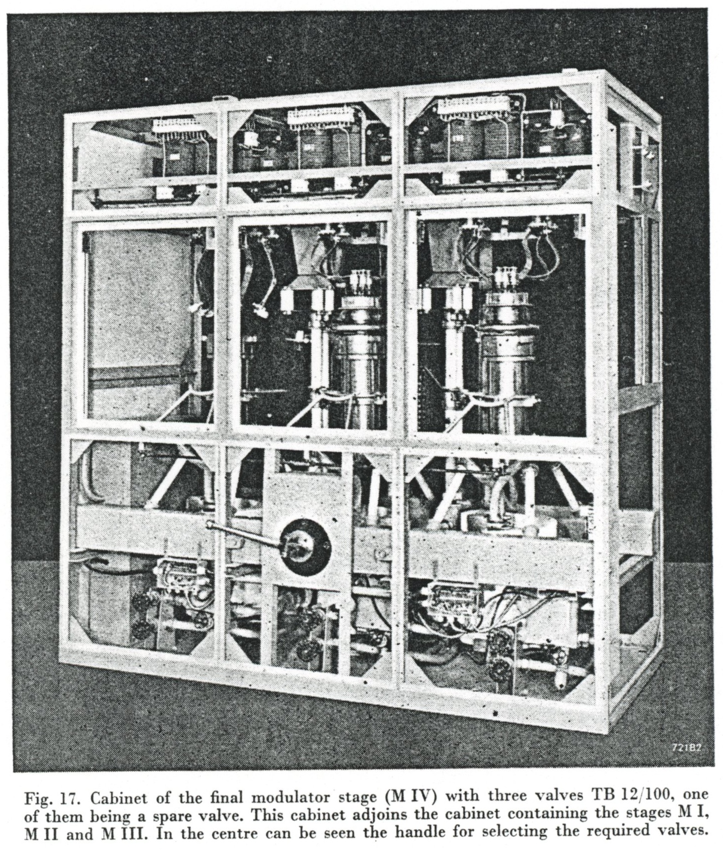
 The valve complement comprises three valves, two of which normally are in operation while the third is used as a spare valve. This is shown in fig. 17 (the valve in the left section has been removed). Change-over switches, controlled by one handle, allow the spare valve to be placed in circuit during operation within one minute. Interruption of a program as a result of a faulty valve is thus limited to only a few minutes. The change-over switches are controlled by a handle, visible on the foreground of fig. 17. By pushing this handle forward, all high voltages are automatically switched off and all condensers shorted. In this
position, the handle can be rotated through an angle of 2 x 90°. The position of the handle shown in fig. 17 corresponds with the left valve and the centre valve in operation. After the handle has been pushed inward and rotated through an angle of 90°, and then pulled out, the two outer valves are ready for operation. By rotating the handle through an angle of 180° instead of 90°, the right and the centre valves are ready for operation.
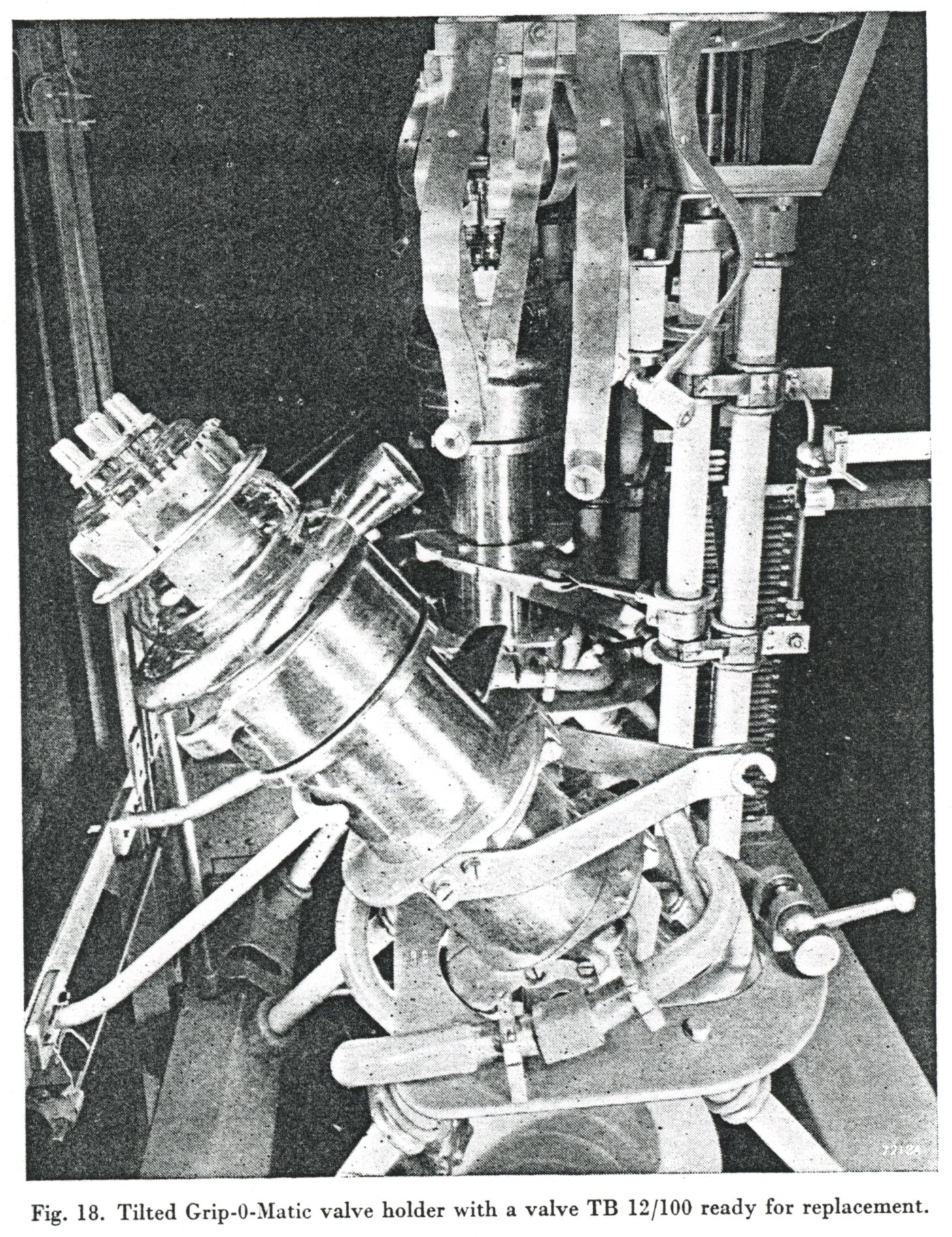
When a valve must be replaced, the handle must be pushed inward which results, as already mentioned, in switching off dangerous voltages and removal of the charges on the condensers.
After the manipulation, a locking mechanism must be loosened to allow the removal of the screenplates in front of the valve to be replaced.
After that, the cradle of the valve can be tilted (figs. 17 and 18). Since in this stage too, the Grip-O-Matic cooler is applied, replacement of a valve is reduced to a very simple manipulation. Fig. 18 shows the valve arrangement; the cradle of the valve holder is tilted and all is ready for replacement of the valve. In this figure are also visible the change-over contacts of the anode (partially
shown).
The valve complement comprises three valves, two of which normally are in operation while the third is used as a spare valve. This is shown in fig. 17 (the valve in the left section has been removed). Change-over switches, controlled by one handle, allow the spare valve to be placed in circuit during operation within one minute. Interruption of a program as a result of a faulty valve is thus limited to only a few minutes. The change-over switches are controlled by a handle, visible on the foreground of fig. 17. By pushing this handle forward, all high voltages are automatically switched off and all condensers shorted. In this
position, the handle can be rotated through an angle of 2 x 90°. The position of the handle shown in fig. 17 corresponds with the left valve and the centre valve in operation. After the handle has been pushed inward and rotated through an angle of 90°, and then pulled out, the two outer valves are ready for operation. By rotating the handle through an angle of 180° instead of 90°, the right and the centre valves are ready for operation.
When a valve must be replaced, the handle must be pushed inward which results, as already mentioned, in switching off dangerous voltages and removal of the charges on the condensers.
After the manipulation, a locking mechanism must be loosened to allow the removal of the screenplates in front of the valve to be replaced.
After that, the cradle of the valve can be tilted (figs. 17 and 18). Since in this stage too, the Grip-O-Matic cooler is applied, replacement of a valve is reduced to a very simple manipulation. Fig. 18 shows the valve arrangement; the cradle of the valve holder is tilted and all is ready for replacement of the valve. In this figure are also visible the change-over contacts of the anode (partially
shown).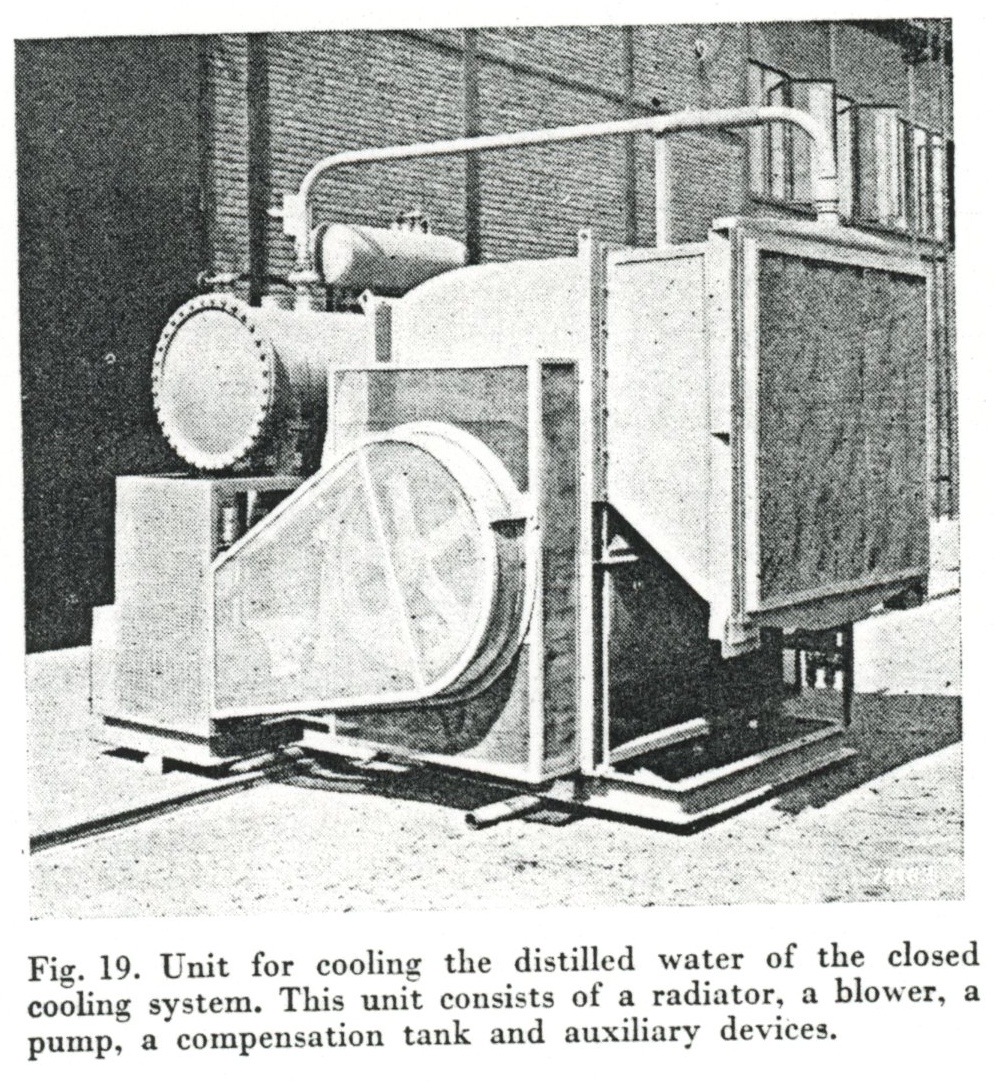 In order to reduce corrosion, the closed cooling system for the transmitting valves TAW 12/10 and TBW 12/100 is operated with distilled water.
Moreover, thoughout the cooling system, copper pipes, copper accessories and bronze conical fittings, joining the various pipes, prevent electrolysis.
In order to reduce corrosion, the closed cooling system for the transmitting valves TAW 12/10 and TBW 12/100 is operated with distilled water.
Moreover, thoughout the cooling system, copper pipes, copper accessories and bronze conical fittings, joining the various pipes, prevent electrolysis.