PHILIPS 8FZ 521 (FB 010)

GENERAL DESCRIPTION


photo Philips 8FZ 521 (FB 010) 
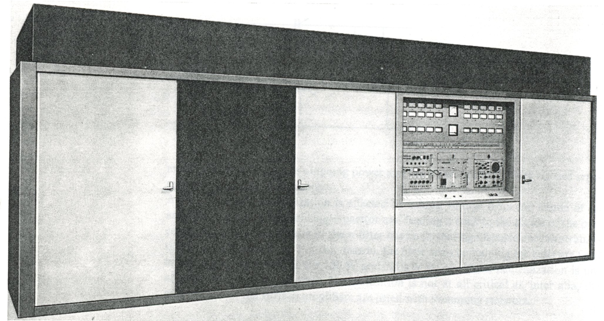
300 kW SHORT-WAVE BROADCAST TRANSMITTER TYPE 8FZ 521 (FB 010)

General

The new 300 kW short-wave broadcast transmitter type FB 010 is designed for the transmission of broadcast programs in the short-wave bands of the 3.2-26.1 MHz frequency range. It is suitable for continuous operation, and is fully tropicalized. This transmmitter is an extension of the range short-wave broadcast transmitters. The design not only incorporates the experience gained with previous models in this range, but is also based upon the latest international regulations and recommendations of CCIR and ITU.

The use of vapour-cooled power tetrodes and silicon rectifiers both for the auxiliary supplies and for the HT supply has resulted in a design offering high overall efficiency and high reliability.

The use of vapour-cooled tetrodes in the last HF stage offers the following features: Careful study has been given to the question of access to individual stages and supply unitsm with the result that tube replacement etc. can be effected safely and rapidly. All operating controls are fitted on the front panelm so that no separate control console is neededm although one can be supplied on special request.

Description

The transmitter is made up of an RF section, an AF section and a power supply section. A decade exciter is used and followed by two driver stages using two pentodes in the first and two tetrodes in the second stage which are connected in parallel. The tuning procedure has been considerably simplified and lends itself well to automatic tuning systems.

The pre-stage which supplies the driving power of approx. 7.5 kW comprises vapotron type tubes to ensure uniform cooling of the power tubes.

The RF power stage is equipped with two vapour-cooled tetrodes, which are connected in parallel.

The AF section contains three balanced amplifier stages, viz.: two input amplifiers and a power stage which is equipped with 2 vapour-cooled tetrodes.

The AF input signal enters the first amplifier stage via an input control and a 10 kHz low-power filter. The level at the input control is shown on a level indicator.

In this design the usual cathode-follower is not necessary because the final tubes are exited without grid current.

This makes for a saving in tubes.

Negative feedback is applied from the modulator anodes to the grids of the input amplifier tubes by means of a frequency-independent network.

Power for the different sections is supplied by the power supply section which comprises five silicon rectifiers.

Features of silicon rectifiers as used as well in the auxiliary supplies as in the HT supply are: A high-speed trip circuit operates in conjuction with the HT-rectifier; ensuring that the transmitter equipment will not be damaged during operation; transients will cause hardly any interruption of the programme.

This protection circuit is equipped with transistorized multivibrator circuits, so that in the event of trouble, such as overloading of the transmitting tubes, unwanted reflections in the feeder etd, the high tension is reduced to zero within about 0.01 sec.

Within 1 sec. the high tension is restored to its nominal value. If the trouble persists, the process is twice repeated after which the circuit breaker operates, switches the equipment off and energizes an alarm device.

Mechanical design

The FB 010 transmitter is housed in an attractively styled cabinet which consists of three partsm to be installed on a floor without special foundation beams and readily attached to each other.

Prefabricated wiring facilitates the installation of electrical connections between three cabinets.

To facilitate inspection and maintenance, great stress has been placed on ease of access. The transmitter cabinet has many doors at all sides, giving access to the various compartments.

The heat exchanger for cooling the water vapour is available in various versions at the customer's choice; forced air-cooling, water-cooling or a combination of both. The whole assembly can be set up on the floor.

TECHNICAL SPECIFICATIONS
Frequency range 3.2-26.1 MHz.
Frequency stability better than 5.10-7 with built-in decade exciter.
Carrier power output 300 kW.
Output impedance 50 ohms unbalanced coaxial output on request: 300 ohms balanced.
Standing wave ratio max. 1 : 1.8.
Spurious emission according to CCIR recommendations.
AF input impedance approx. 600 ohms balanced.
AF input level adjustable between 0 and +20 dBm at 100% modulation (1000 Hz); 0 dBm = 1 mW into 600 ohms.
Linear distortion flat within ±1 dB between 50 and 10,000 Hz with reference to 1000 Hz at 60% modulation.
Non-linear distortion less than 3% from 100-3000 Hz; less than 4% from 50-100 Hz and from 3000 to 10,000 Hz at modulation depths up to 90%.
Hum-noise level less than -60 dB; weigthed value less than -70 dB referred to level for 100% modulation.
Carrier amplitude drop less than 5% up to a maximum modulation depth of 95%.
Max. depth of modulation 100%
Power supply nominally 3 x 380 V four-wire for teh auxiliary supplies and 3 x 10 kV three-wire for the HT rectifier; adaptation to other voltages on request.
Power factor 0.9 average.
Ambient temperature at sea level: 0°C to +45°C; at 2000 m (6600 ft): max. +35°C
Relative humidity max. 95%.
Dimensions (transmitter cabinet) height 242 cm (95 in.); width 814 cm (320 in.); depth 230 cm (90 in.).
Weight (transmitter cabinet) 9500 kg (20,947 lb.) unpacked.

TUBE COMPLEMENT
RF stages AF stages and modulator Rectifiers
Number Type Number Type Number Type
2 YL 1091 2 YL 1091

2 YL 1182 2 YL 1150

2 YL 1150 2 E80L (6227)

2 E810F


THIS TYPE OF TRANSMITTER IS INSTALLED IN THE FOLLOWING COUNTRIES

ITU Country
ITU Country
flag ISR ISR ISRAEL flag MDG MDG MADAGASCAR
flag HOL HOL NETHERLANDS