PHILIPS 8FZ 514

GENERAL DESCRIPTION


photo Philips 8FZ 514 
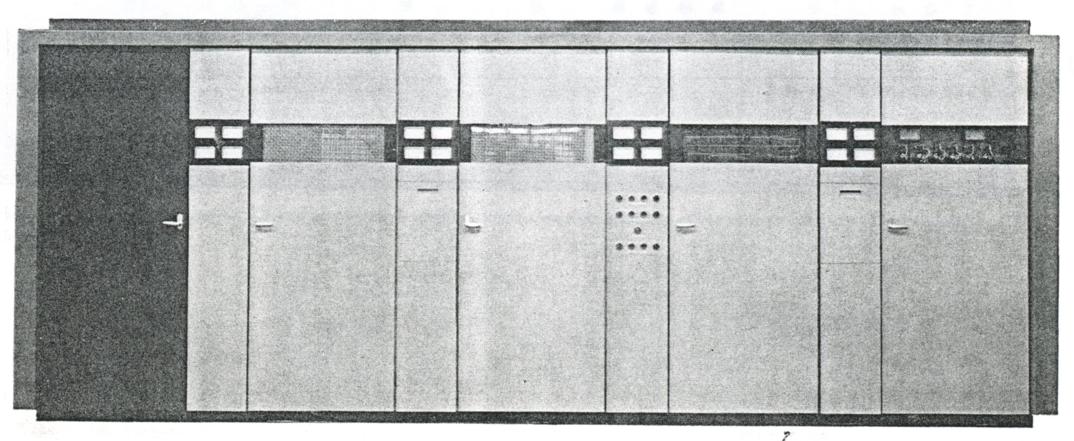
50 kW AM SHORT-WAVE BROADCAST TRANSMITTER TYPE 8FZ 514

General

This new powerful broadcast transmitter embodies the latest developments in engineering and styling and combines excellent qualities with an attractive appearance.

It permits continuous tuning in the 3.2-26.1 Mc/s broadcasting bands. A built-in crystal oscillator offers a choice of 10 crystal-controlled frequencies. (A variable-frequency oscillator (VFO) can be incorporated if required.)

The operating costs are lower owing to the overall efficiency, which has been raised to a maximum and the number of tubes and tube types, which has been minimized (low running costs and only three DC supplies).

The transmitter is suitable for continuous operation and it is fully tropicalized. Other technical requirements such as audio response, distortion figures, dependability, and stability of the power stage satisfy the highest requirements.

Extensive safety devices are incorporated to protect staff and equipment from the dangers of HT and overloads.

Description

The transmitter is made up of an RF section (exciter stage—pre-stage—power stage), an AF section and a power supply section.

The exciter stage comprises a crystal oscillator and three broadband amplifiers. The crystal oscillator offers a choice of 10 switch-selected crystals. The three amplifiers operate either as straight amplifiers or as frequency doublers, depending on the frequency selected.

The pre-stage comprises three amplifiers, each of which has balanced grid and anode circuits permitting continuous tuning.

The power stage is designed on a push-pull basis and makes use of grounded-grid operation. The AF section comprises four balanced amplifier stages; the AF input signal enters the first amplifier stage via an input control and a 10 kc/s low-pass filter.

Negative feedback is applied from the modulator anodes to the grids of the input amplifier tubes by means of a frequency-independent network. Power for the various sections is supplied by a three-phase grid bias rectifier (-300V), a three-phase rectifier (+800 V) and an HT rectifier (10/5 kV). Despite its high power, the transmitter is easily operated by means of three pairs of pushbuttons as the front. Once these pushbuttons have been operated, the auxiliary circuits are all switched on automatically, the whole switching procedure being made visible on a mimic diagram. All necessary controls and full-metering facilities are built-in.

The automatic switching and safety systems give full protection in the event of mistakes in operation or failures. When failures or disturbances occur, the high tension is reduced to zero for a very short time and then switched on automatically again. This cycle is carried out three times, after which the transmitter is switched off definitely if the fault has not been renedied.

An operator's console can be supplied as an optional extra.

Mechanical design

The type 8FZ 514 transmitter is housed in a nicely styled cabinet divided into identical compartments, with five doors at the front and back. The first door encloses the preliminary RF stages; these are separated from the RF power stages which occupy the space enclosed behind the next two doors. The last two compartments house the AF sections and the power supply equipment.

This layout gives easy access to the various parts of the equipment and also facilitates the replacement of tubes.

To reduce the cost of installation to a minimum, the cabinet, though completely assembled in the factory, can be takem apart into sections which are then bolted together on the installation site.

The blower for cooling the power tubes can be installed at low cost either in a separate room on the ground floor or in a basement under the transmitter room.

TECHNICAL SPECIFICATIONS
Frequency range any frequency in the 3.2-26.1 Mc/s broadcast bands
Frequency stability better than 15.10-6 with built-in crystal oscillator, complying with Radio Regulations, Geneva 1959
Frequency selection one of up to ten crystal-controlled frequencies
Carrier power output 50 kW
Output impedance 320 ohms balanced
Standing wave ratio max. 1 : 1.4
Spurious emission less than 50 mW, complying with Radio Regulations, Geneva 1959
AF input impedance approx. 600 ohms balanced
AF input level Adjustable between 0 dBm and +20 dBm at 100% modulation (1000 c/s); 0 dBm = 1 mW into 600 ohms
Linear distortion flat within ±1 dB between 30 and 10,000 c/s with reference to 1000 c/s at 60% modulation
Non-linear distortion less than 2% from 100 to 3000 c/s; less than 3% from 50 to 10,000 c/s at modulation depths up to 90%. If desired, 3% from 30 to 10,000 c/s
Hum noise level less than -60 dB; weigthed value less than -70 dB (CCIF curve) referred to level for 100% modulation
Carrier amplitude drop less than 5% up to a maximum modulation depth of 95%
Max. depth of modulation 100%
Power supply 3 x 380 V ±5% with neutral, 50 or 60 c/s ±2%.
Power factor 0.9 average
Ambient temperature at sea level: +10° to +45° C; at 2000 m (6600 ft.): +10° to +35° C
Relative humidity max. 95%
Dimensions (transmitter cabinet) height 235 cm (7'8")
width 602 cm (19'9")
depth 210 cm (6'10½")
Weight 14,000 kg (30,000 lb.) unpacked

TUBE COMPLEMENT
RF stages AF stages and modulator Rectifiers
Number Type Number Type Number Type
2 TBL12/40 2 TBL12/40 6 DCG7/100
4 QBL5/3500 (6076) 2 TB2.5/400 6 E80L (6227)
5 QQE06/40 (5894) 8 QE08/200

4 E80L (6227) 2 E80L (6227)


THIS TYPE OF TRANSMITTER IS INSTALLED IN THE FOLLOWING COUNTRIES

ITU Country
ITU Country
flag CBG CBG CAMBODIA flag INS INS INDONESIA
flag OMA OMA OMAN flag RRW RRW RWANDA
flag TGO TGO TOGO