PHILIPS 8FZ 503 / 8FZ 512

GENERAL DESCRIPTION


photo Philips 8FZ 503 / 8FZ 512 
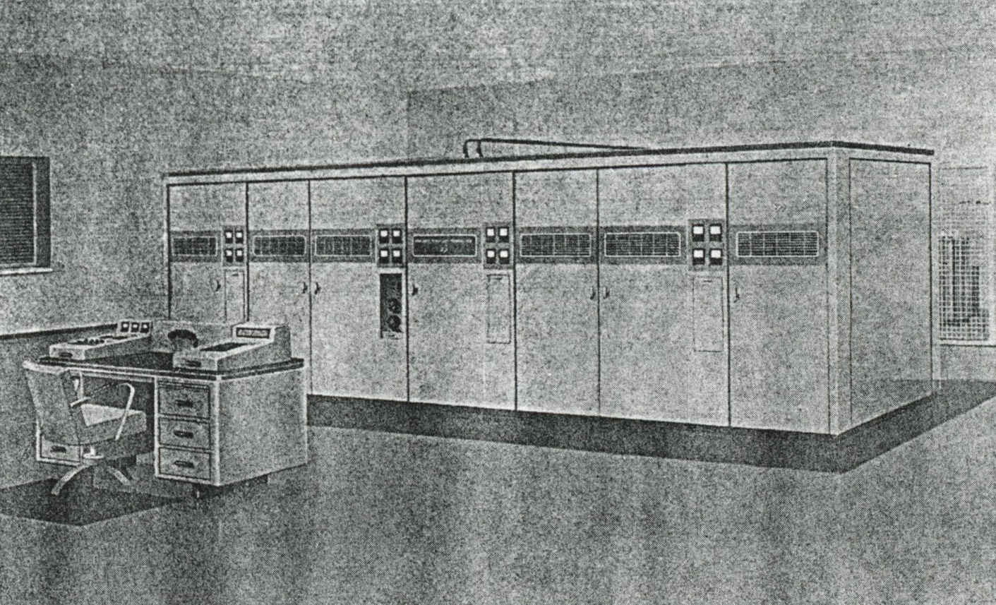
120 kW AM SHORT-WAVE BROADCAST TRANSMITTER TYPES 8FZ 503 AND 8FZ 512

General

A very powerful transmitter, continuously tunable in the range 5.9-26.1 Mc/s (type 8FZ 503) or, to special order, 3.2-26.1 Mc/s (type 8FZ 512). The design is exceptionally well suited for continuous operation: maintenance requirements are a minimum and extensive high-speed safety devices have been incorporated. The high efficiency of the transmitter, obtained by the use of modern high-gain tubes throughout, ensures economic operation.

Description

The transmitter is driven by a crystal oscillator in the built-in exciter unit so that the frequency stability laid down by the CCIR is obtained. With this crystal oscillator a choice of up to 10 interchangeable crystals is possible. If greater stability is desired, a bay with up to 8 stable oscillators can be supplied optionally.

The output stage is driven via several intermediate stages, reduced in number owing to the use of high-gain tetrodes. The output stage itself employs Lecher tuned circuits. The controls for these and the other circuits are all fitted on the front panels, so that with the aid of a tuning table the transmitter can be tuned in several minutes. The modulator is designed on a push-pull basis and makes effective use of negative feed-back. The result is excellent audio quality.

Despite its high power the transmitter is easily operated by means of a few push-buttons. All necessary controls and full metering facilities are built in. An operator's console can be upplied optionally.

The automatic switching and safety system gives full protection in the event of mistakes in operation or failures. When failures or disturbances of short duration occur the high tension is interrupted for a very short time and then switched on automatically again. This cycle is carried out three times after which the transmitter is definitely switched off if the fault is not cured.

Mechanical design

Its front panel gives this imposing transmitter a handsome appearance. It is fitted with doors and clearly visible meters. Behind the façade stands a cubicle housing the RF components, the modulator cabinet and the HT rectifier.

The cubicle can be divided into two parts for the purpose of transport. Separate elements, such as the HT and modulation transformers, are set up behind the cubicle, but they may also be housed in a special room or cellar. All parts of the transmitter are easily accessible via doors, slide-out chassis, etc. provided where appropriate with safety interlocks. The blowers are housed in another room.

Full instructions for intallation, operation and maintenance are supplied in the form of manuals. Assembly is a relatively simple job for which no special tools are necessary.

The entire transmitter is tropic-proof, and parts and tubes are conservatively rated.

Transmitter name-plates and instruction manuals are normally supplied in English; other languages (e.g. Spanish) are available on request.

TECHNICAL SPECIFICATIONS
Frequency range type 8FZ 503: 5.9-26.1 Mc/s
type 8FZ 512: 3.2-26.1 Mc/s
Frequency tolerance with internal exciter 15.10-6; with optional external oscillator 1.10-6
RF output power 120 kW (carrier)
RF output impedance 320 ohms balanced
Standing wave ratio max. 1.4:1
Spurious radiation according to CCIR recommendations
AF input impedance nominal 600 ohms balanced
AF input level adjustable between 0 and +20 dBm, reference 1000 c/s at 100% modulation; 0 dBm = 1 mW into 600 ohms
Linear distortion within ±1 dB from 30-10,000 c/s, reference to 1000 c/s at 60% modulation
Non-linear distortion less than 2% from 100-3000 c/s at 90% modulation and 3% from 50-10,000 c/s; if required less than 3% from 30-10,000 c/s
Noise level better than -60 dB, unweigthed; reference 1000 c/s at 100% modulation
Modulation capability 100%
Power consumption at 0% modulation approx. 210 kW
at 30% modulation approx. 235 kW
at 100% modulation approx. 300 kW
Power factor approx. 0.9
Ambient temperature at sea level: +10° to +45° C under tropical conditions; at 6000 ft: +10° to +35° C
Relative humidity up to 95%
Dimensions transmitter proper: height 220 cm (88 in.); width 885 cm (354 in.); depth 200 cm (80 in.)
Minimum floorspace 1100 x 650 cm (36 x 21 ft)
Weight (approx.) 30,000 kg (66,000 lb.) unpacked

TUBE COMPLEMENT
RF stages, AF stages and modulator Rectifiers
Number Type Number Type
4 TBL12/40 6 DCG7/100
2 TBL12/100 (6078) 1 QE06/50 (807)
2 QBL5/3500 (6076) 3 5Y3GT
10 QE08/200 2 6AQ5
3 QQE06/40 (5894) 6 E80L (6227)
6 E80L (6227)


THIS TYPE OF TRANSMITTER IS INSTALLED IN THE FOLLOWING COUNTRIES

ITU Country
ITU Country