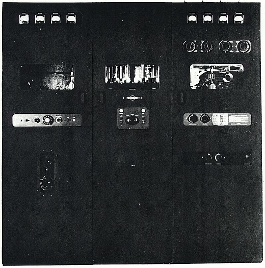
COLLINS 231D-20

GENERAL DESCRIPTION


photo Collins 231D-20 EQUIPMENT

This equipment has been designed for applications involving point-to-point communication, aeronautical ground stations and other services requiring operation on a number of readily selected frequency channels. The transmitter is equipped with the Collins Autotune system which permits the selection of any one of ten pretuned frequency channels by the operation of a telephone dial on the transmitter control panel or a dial located on the remote control unit.

TRANSMITTER

The transmitter is contained in three bays or cabinets and requires a space 31" deep by 82-1/6" wide by 95-5/8" high and enough additional space to permit free circulation of air and the making of antenna and ground connections. The cabinets are finished with a zinc chromate primer and a final coat of black crinkle on the outside and are painted flat gray on the inside. The Collins Type 1016-5 Radio Transmitter cabinet contains all r-f units and the Autotune control system. The Collins Type 1100-2 Rectifier Power Unit cabinet contains the bias, low voltage and high voltage power supplies and all transmitter power controls. The Collins Type 1025-4 Modulator cabinet contains the speech amplifier, audio driver and modulator circuit components. Each of the cabinets is equipped with full length front and rear doors. All three cabinets are equipped with door interlock switches so that power is immediately removed when either a front or rear door is opened. Glass windows in the front door of the r-f and audio bays permit viewing all indicating instruments without opening cabinet doors. All Autotune control knobs are accessible through openings in the front doors of the transmitter cabinet so that tuning adjustments may be made without opening the doors.

All three bays are ventilated by a blower located in the base of the Collins Type 1025-4 Modulator cabinet. The air is forced into the power and r-f bays through ducts located in the bases of the cabinet. The air is exhausted in such a manner that dust is not permitted to settle on the transmitter components.

The following paragraphs give a brief description of the various units comprising the transmitter:

  1. Output Network.
    This unit contains the components of the output balancing network and the pi network that is used as a combination power amplifier plate tank and antenna coupling circuit. The three variable capacitors, the SPDT switch and the two tap switches are driven by heavy-duty singleturn units that are associated with the Autotune system.

  2. Power Amplifier Unit.
    The power amplifier tubes, the intermediate amplifier plate tank circuit and a stabilizer circuit are contained in this unit. The network contained in this unit is a combination intermediate amplifier plate tank and power amplifier grid circuit. The tank circuit utilizes a pair of tapped inductors and two variable capacitors to make up a balanced tank circuit. The variable capacitor and inductor tap switch are driven by singleturn units. The stabilizing circuit utilizes a Type 811 triode as an electronic load on the grid circuit of the power amplifier tubes.

  3. R-F Exciter Unit.
    The remaining r-f circuit components are contained in this unit. Two singleturn units, associated with the Autotune system, drive the variable components within the unit. One singleturn unit drives the exciter plate tank tuning capacitors and the other singleturn unit drives the exciter band switch sections. Components within the r-f unit have been carefully placed and shielded to obtain the best possible performance. The plate mounted near the intermediate amplifier tubes is used as a neutralizing capacitor. Filament voltages for tubes within the unit are supplied by three transformers mounted on the unit chassis. All connections to this unit except those to the plate caps of the intermediate amplifier tubes are made by two plug-in connectors on the rear of the chassis.

  4. Autotune Control Unit.
    All of the Autotune system control relays are mounted in this unit. All these relays are of the 48-volt d-c type and are supplied with voltage by a dry disk rectifier that is mounted on the power chassis. All connections to this unit are made by two plug-in connectors that are located on the rear of the chassis.

  5. Power Unit.
    All power supplies and all power controls are mounted on the vertical chassis that makes up the power unit. Four rectifiers supplies furnish all voltages for operation of both r-f and audio circuits within the transmitter. The relay supply utilizes a dry-disk rectifier to obtain the 48 volts dc. Two autotransformers are located near the bottom of the vertical chassis. Terminals of the transformers are brought out through the front of the chassis so that adjustments may be made to compensate for low or high power source voltage. A panel, mounted near the center of the unit, contains all of the power controls. The high voltage plate transformer mounts behind the vertical chassis.

  6. Modulator and Audio Driver Unit.
    This unit contains the components of the cathode-coupled audio driver and modulator stages and the hand-set coupling transformer. Components in this unit are mounted on a chassis that is bolted into the modulator cabinet. All connections are made by means of cables. The transformer that supplies voltage for filaments of the audio driver tubes is mounted in this unit but the transformer that supplies voltage for the modulator tubes is mounted on a separate chassis.

  7. Speech Amplifier Unit.
    This unit contains the first, second, and third audio amplifier stages, the audio limiter and audio squelch circuits and the MCW oscillator circuit. Four controls on the front of the chassis control the MCW frequency, MCW gain, audio gain and limiter gain. The local-remote switch, the test switch, the telephone dial, the key jack, and microphone jack are also mounted on this unit. Connections to the unit are made by two plugs that are mounted on the rear of the chassis. Filament voltages for all tubes in this unit are supplied by a transformer that is mounted on a chassis with the modulator filament transformer.

  8. Base Components.
    The PHONE-CW relay, the intermediate voltage filter capacitor and the high voltage filter capacitor are mounted in the base of the Collins Type 1016-5 Radio Transmitter cabinet. The modulation transformer and the ventilating blower are mounted in the base of the Collins Type 1025-4 Modulator cabinet.
REMOTE CONTROL UNIT

Panels of the remote control units are finished in flat black and the chassis finished in flat gray. This unit may be located at any distance from the transmitter up to the distance for which the line loss becomes greater than 25 db or the resistance of the line loop becomes greater than 1000 ohms. This unit may be used to control all functions of the transmitter. The power supply for the tubes is contained within the unit and is designed for operation from a 115-volt 50/60-cps single-phase power source.

POWER SOURCE

The transmitting equipment proper is designed to operate from a 230-volt 50/60-cps 3-phase power source. The equipment draws a maximum of 30 amperes when operating with full 3-kw output. The power required under varying operating conditions is tabulated below:
Condition Power Input
CW - Standby 1840 watts
VOICE & MCW - Standby 3160 watts
CW - Key Closed 6480 watts
MCW - Key Closed 7240 watts
VOICE - 100 Modulation 9920 watts

The remote control unit is designed to operate from a 115-volt 50/60-cps single-phase power source and requires approximately 52 watts for normal operation. The power factor in all cases is approximately 85%.

POWER OUTPUT

Nominal power output of the 231D-20 is 3 kw. For CW only, power output of 4 kw is available.

TYPE OF EMISSION

CW (A1), MCW (A2), and VOICE (A3) emissions are available with this equipment. Electronic carrier control is used and permits keying speeds of up to two hundred words per minute with A1 emission and keying speeds up to sixty words per minute with A2 emission. The modulation frequency for A2 emission is variable in seven steps in the range 400 cps to 1200 cps.

FREQUENCY RANGE

The equipment is capable of operation on any frequency within the range of 3000 kc to 26,000 kc. The power amplifier output coupling network is designed to work into unbalanced antennas or transmission lines having impedances of from 50 to 1200 ohms with a phase angle of 0°, 70 to 850 ohms with a phase angle of ±45° and 100 to 600 ohms with a phase angle of ±60°. A balancing network is available which will permit operation into a balanced transmission line of 300 to 1200 ohms resistive, with a standing wave of up to 2 to 1 ratio.

FREQUENCY CHANGE SYSTEM

The equipment employs tne Collins Autotune system of frequency selection. The Autotune system provides for fast frequency change by mechanical repositioning of the various tuning elements to present positions. The positioning elements are driven by a single motor which is controlled by a series of interlocking relays. The whole system will operate to change the frequency of transmission within a period of ten seconds. Any one of ten frequency channels or manual tuning may be selected by dialing.

The Autotune mechanisms are constructed with mechanical play and therefore can have two extreme rotational settings when locked. All dials, when operated automatically, approach the calibrated setting in a clockwise direction. Reset accuracy is thus assured, provided that in the preliminary manual tuning, the final direction of rotation is also in a clockwise direction.

FREQUENCY CONTROL

The frequency of the r-f output is controlled by a crystal. Any one of ten crystals can be selected by the Autotune system.

AUDIO CHARACTERISTICS

The overall frequency response, as measured between 500-ohm input and the rectified carrier output, is uniform within 3 db from 150 cps to 3500 cps. The compression circuit has negligible effect with modulation levels below 70% modulation. For modulation levels above 70%, a change of 10 db in input level will cause a change in output level that does not exceed 3 db. The noise on the carrier, with a 500-ohm resistor connected across the audio input circuit, is more than 40 db below 100% modulation level. The harmonic distortion with 100% modulation does not exceed 10% input at 400 cps. The audio input ranges from 0 to -25 db for 100% modulation. The noise level is at least 40 db below 100% modulation.

PANEL CONTROL

Panel controls on the transmitter consist of a telephone dial for selecting frequency channels and type of emission, a power level switch, a local-remote switch, filament and plate power switches, a test key switch, a telegraph key cord plug receptacle and a microphone cord plug receptacle. The above controls permit the operator to apply or remove power, and to control the emission from a position adjacent to the transmitter proper.

REMOTE CONTROL

The remote control unit permits an operator to perform all operations that are necessary to select the frequency channel and type of emission, to control the emission, and to turn the transmitter on and off from any distance up to the distance where the resistance of the remote line loop becomes greater than 1000 ohms or the loss in the line exceeds 25 db. All of the above functions except control of the carrier are performed by dialing. The control system requires two cable pairs and a ground return circuit. A receiver-disabling circuit has been incorporated in the control unit to disable the receiver when the transmitter carrier is on.

60 TO 50 CPS CONVERSION KIT

A conversion kit allows the transmitter to be converted from 60-cps operation to 50-cps operation. Coils must be removed from K-202, K-203, K-205 and replaced with 50-cps coils.

TUBE COMPLEMENT
RF stages AF stages and modulator Rectifiers
Number Type Number Type Number Type
1 811 2 450TL 4 866/866A
2 750TL 2 845 6 4B32
2 4-125A 2 801

1 807 1 6X5GT

1 837 1 6SN7GT

1 6SJ7 1 6SJ7

1 6X5GT 2 6C8G


1 6SL7GT


THIS TYPE OF TRANSMITTER IS INSTALLED IN THE FOLLOWING COUNTRIES

ITU Country
ITU Country
flag D D GERMANY flag INS INS INDONESIA
flag MRC MRC MOROCCO flag POR POR PORTUGAL
flag SEY SEY SEYCHELLES flag USA USA USA