BAUER 710C

GENERAL DESCRIPTION


Model 710C AM Transmitter, 10000 watts

Bauer 710C OPERATIONAL BENEFITS
GENERAL

Elcom • Bauer Models 705C-710C-715C make up a family of medium-power AM transmitters over a nominal output power range of 5000 watts to 15000 watts. 705C is offered with a standard power cutback to either 1000 watts or 500 watts; a 2500 watt power cutback is available at a slight additional charge. 710C and 715C have a standard power cutback to 1/4 power for tuning and testing.

705C, 710C and 715C are contained in dual-width cabinets; the 715C also includes a high-voltage vault.

Bauer 710C 
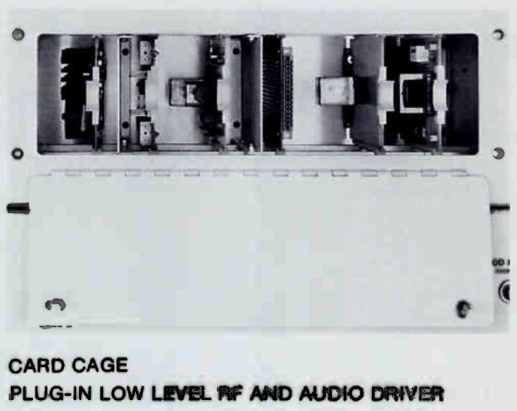
OSCILLATOR, RF DRIVER and AUDIO DRIVER

The master RF oscillator uses an ovenless crystal that operates at four times carrier frequency for maximum stability. A solid state amplifier is used to drive a highly efficient two-transistor RF stage, operating Class D, which then feeds the final amplifier. The audio driver section consists of a solid state, push-pull Class B audio amplifier. Audio drive, RF drive and all tube plate voltages are reduced for low power operation. All of the low level solid state circuitry are located on individual plug-in printed circuit boards conveniently accessible from the front panel.

Bauer 710C 
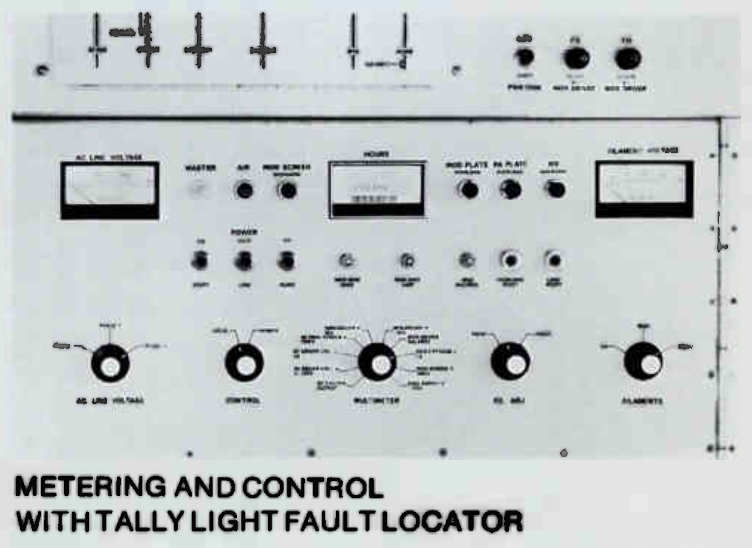
METERING, CONTROL and PROTECTION CIRCUITS

Metering for all important operating parameters, including filament operating hours, plate voltages and currents, line voltages and RF output, is included. Optional remote metering can be provided if desired, as remote metering sampling is standard.

All control circuitry is easily accessible through a front swingout panel. The appropriate control functions for ATS or remote control are available via barrier strips. A four-function remote control interface is factory-installed. A solid state control system, utilizing diode-logic and relays, incorporates full overload protection. A tally light fault locator memory system with three-step overload recycling is standard, providing quick restart on momentary outages with full transmitter protection. The tally light system allows remote fault resetting while indicating where the fault occurred.

Bauer 710C 
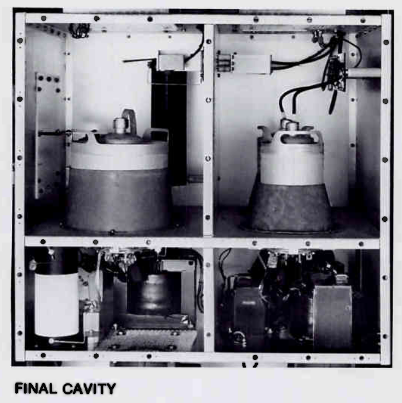
POWER AMPLIFIER and MODULATOR

The 705C RF power amplifier consists of a single 4CX5000A tetrode tube, while the 710C and 715C use a single 4CX15000A tetrode tube. The RF power amplifiers on all models are operated Class C, and are plate modulated.

The audio modulator for the 705C, 710C and 715C transmitters consists of two type 4CX5000A tetrode tubes, operated push-pull in Class AB-1. A large oil-filled modulation transformer is standard, as is vacuum capacitor final output plate tuning. All models are easily capable of 125% positive modulation and can be used with the latest audio processing systems.

This amplifier modulator system is inherently stable and tolerant of antenna system impedance variations.

Bauer 710C 
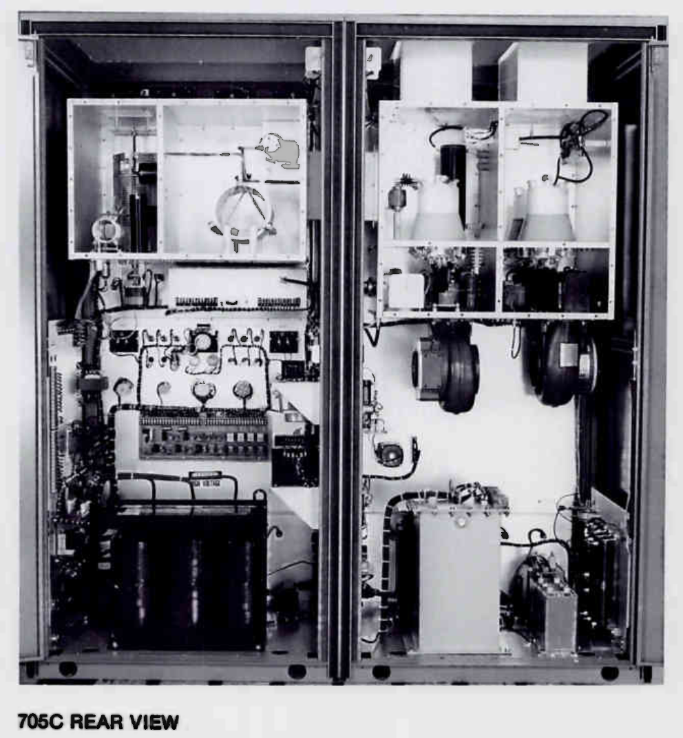
POWER SUPPLY and CABINETS

Step-start high-voltage switching, which allows the transmitter to cycle through low power output before high power output is energized, is standard except on 408-volt primary systems. (Contact the factory for details on 408-volt operation.)

Solid state rectification is used exclusively in all transmitter power supplies. All power supply components are conservatively rated and easily accessible through the rear door of the power supply cabinet, which is interlocked. Full-length, non-interlocked front doors and side panels, which may be removed if necessary, are provided on the cabinets along with interlocked rear doors that remove primary voltage and bleed down high voltage instantly. Grounded shorting sticks are also provided as an additional precaution.

Bauer 710C diagram
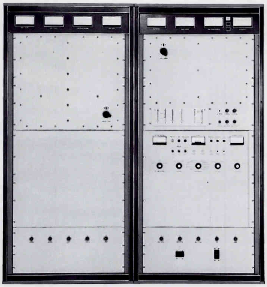
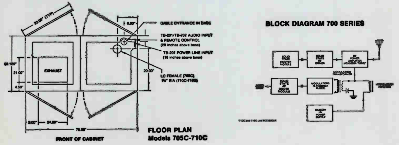
TECHNICAL SPECIFICATIONS
Power Output Nominal: 10000 W
Maximum: 12000 W
Power Supply 208-240 VAC 50/60 Hz, 3 phase
Other line voltages on request
Power Consumption Zero Modulation: 19000 W
Average Modulation: 22000 W
>100% Modulation: 27000 W
Power Factor 0.9
Output Impedance 50 Ohms, nominal
Audio Input Impedance 600 Ohms, balanced
Audio Input Level +10 dBm ±2 dB for 100% modulation
Audio Frequency Distortion 2% or less (50 Hz to 10 KHz, 95% modulation)
Audio Frequency Response ±1 dB, 50 Hz to 10 KHz
Frequency Stability ±5 Hz
Frequency Range 540 to 1600 KHz
2 MHz - 10 MHz available on request
Noise, referred to 100% modulation Better than -60 dB
Carrier Shift 0-100% modulation: Less than 2%
Output Connector 1⅝" EIA
Weight 2150 lbs. (975 kg)
Size 75"H x 70"W x 30"D
(191 cm H x 178 cm W x 76 cm D)
Maximum Altitude 7500', (2286 meters)
Higher available on special order
Ambient Temperature Range -4°F to 113°F (-20°C to +45°C)
Specifications may change without notice

TUBE COMPLEMENT
RF stages AF stages and modulator
Number Type Number Type
1 4CX15,000A 2 4CX5000A


THIS TYPE OF TRANSMITTER IS INSTALLED IN THE FOLLOWING COUNTRIES

ITU Country
ITU Country
flag BOL BOL BOLIVIA flag EQA EQA ECUADOR
flag USA USA USA