| GENERAL DESCRIPTION |
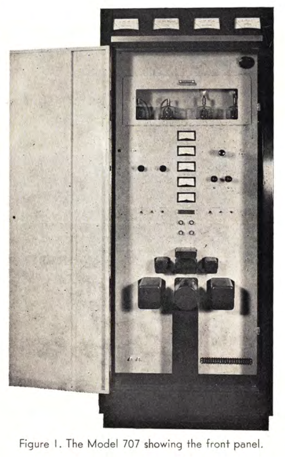 DESIGN FEATURES OF A BROADCAST TRANSMITTER KIT
 The RF Section
 The AF Section
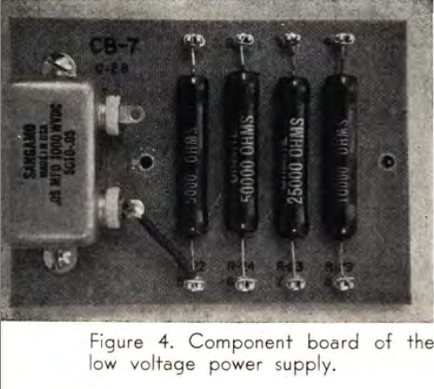 The Power Supplies
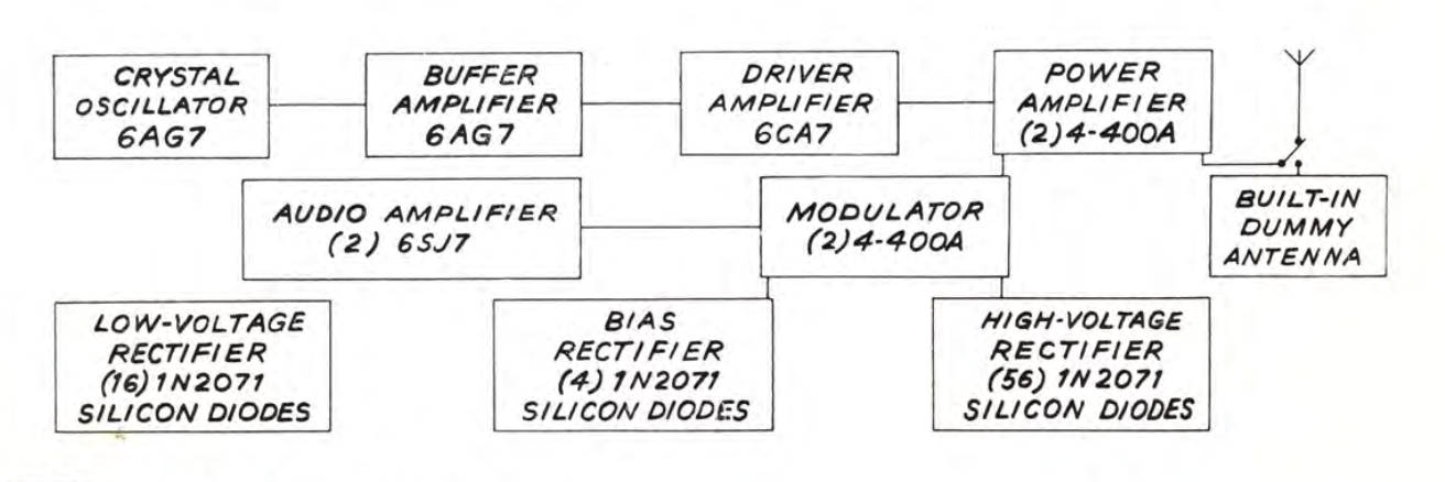
| TECHNICAL SPECIFICATIONS | |
| Type Of Emission | A3 |
| Rated Power Output | 1000/500/250 watts |
| Power Output Capability | 1100 watts |
| R.F. Output Impedance | 50 ohms, unbalanced |
| Frequency Range | 540-1600 Kc |
| Frequency Stability | ±5 cps |
| Audio Input Level (100% mod.) | 10 dbm |
| Frequency Response (0-95% mod.) | 1000/500/250 watts 50-10,000 cps : ±0.5 db 30-12,000 cps : ±1.5 db |
| Distortion (0-95% mod.) | 1000/500/250 watts 50-10,000 cps : 2.0% max |
| Carrier Shift | 1000/500/250 watts less than 3% |
| Noise Level (below 100% mod.) | 1000 and 500 watts : -60 db 250 watts : -57 db |
| Power Consumption | (For one kilowatt carrier power) Average modulation : 3300 watts 100% modulation : 3950 watts |
| Power Requirements | 208-240 volts 50/60 cycles Single phase |
| Dimensions | Height : 75" Width : 30" Depth : 25" |
| Net Weight | 800 pounds (approx.) |
| Specifications may change without notice | |
| TUBE COMPLEMENT | |||
| RF stages | AF stages and modulator | ||
| Number | Type | Number | Type |
| 2 | 4-400A | 2 | 4-400A |
| 3 | 6AG7 | 2 | 6SJ7 |
| THIS TYPE OF TRANSMITTER IS INSTALLED IN THE FOLLOWING COUNTRIES | |||||
| ITU | Country | ITU | Country | ||
| CAN | CANADA | COD | CONGO DEMOCRATIC REPUBLIC | ||
| VEN | VENEZUELA | ||||