RCA BHF-50A

GENERAL DESCRIPTION


TYPE BHF-50A 50 KW HIGH FREQUENCY TRANSMITTER

photo RCA BHF-50A 
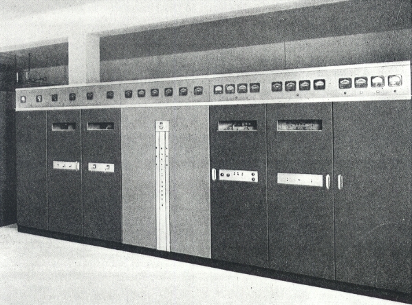
The BHF-50A transmitter is a 50 KW AM High Frequency broadcast transmitter designed for high fidelity service in the International Broadcast bands from 3.0 to 26.1 megacycles. The transmitter is entirely air cooled. The number of tuning adjustments are held to a minimum by the use of grounded grid amplifiers and by the use of ganged circuit elements. The use of remotely controlled motor driven circuit elements permits tuning the transmitter to any frequency within the range of 3.0 to 22 megacycles within an elapsed time of 2 minutes, with slightly longer time required for changing to tho 26.1 band. Features include a unified front, streamline styling, centralized power and control units, and dead front construction.

Mechanical Features

The front panel is 84 inches high and 16 1/2 feet long. The r-f section of the transmitter is placed behind this panel with the exciter and modulator to the right and the 50 KW amplifier and output unit to the left. The 50 KW amplifier is built as one unit comprising the driver and final amplifiers. This amplifier unit, together with the output unit, is set back from the front panel to provide a walkway for inspection, tube changing, etc. Tube changing is facilitated by providing a tube hoist for the 50 KW amplifier tubes, and by the use of quick acting tube connectors.

Tuning controls for the low power r-f stages are located on the exciter unit front, as are the indicating instruments for these stages. Tuning controls for the 50 KW amplifier are centralized on the center section of the front panel together with the indicating instruments associated with these controls. Normal operational controls are located in this same central position.

Installation flexibility is attained by making the r-f and modulating sections an integral unit with interconnecting wiring ducts provided, and considering the power equipment as items which may be strategically placed to avoid building obstructions. The minimum required "one piece" (back of panel) areas is 9 x 19 1/2 feet, and the power equipment may be located, as desired either on the same floor level or in a basement space. Power equipment is constructed in units entirely enclosed and interlocked so that no fences or enclosures are required, other than that required for the oil filled modulator units by local electrical codes. Interconnecting conduit and wire ducts are held to a minimum by enclosing all the main d-c power supplies oil in one unit.

Circuit Description

The exciter unit is housed in a cabinet with front and rear access doors, with all tuning controls and indicating instruments located on the front panel. Three stages of amplification are used to raise the r-f signal from an external source of 1 to 3 watts to the power level necessary to excite the following driver amplifier.

The first amplifier employs an RCA type 4E27A tube operating as a frequency doubler. The external signal is applied to the input circuit of this stage through a 50 to 75 ohm coaxial connection. The plate circuit consists of a variable capacitance and inductance which are ganged and operated simultaneously by the same control.

The second stage (1st RF) has two 4E27A tubes in parallel with ganged inductance and capacitance tuning similar to that used in the doubler stage. The plate circuit is a "pi" type filter circuit with the output capacitor variable from the front panel to control the driving power to the intermediate power amplifier (IPA).

The IPA uses an RCA 5762 external anode air cooled triode, in a grounded grid circuit, and consequently no neutralization is required. The filament is isolated from the 60 cycle power supply by dual chokes and the tube input capacity becomes a part of the output capacitance leg of the 2nd r-f plate circuit. As a result, a low impedance input is assured, and no instability or harmonic resonances were encountered through the use of this essentially direct coupling.

A "pi" network configuration is used for the plate circuit, with the series inductive leg and the input shunt capacitive leg ganged mechanically and front panel controlled. Separate control is provided for the output leg to provide drive adjustment for the driver amplifier. Use of the ganged plate circuit elements and vacuum capacitors allows tuning adjustment over the entire frequency range from a single front panel control.

TUBE COMPLEMENT
RF stages AF stages and modulator Rectifiers
Number Type Number Type Number Type
3 9C25 2 9C25 6 857B
1 5762 8 813 2 8008
3 4E27A 2 4E27A


2 807


THIS TYPE OF TRANSMITTER IS INSTALLED IN THE FOLLOWING COUNTRIES

ITU Country
ITU Country
flag D D GERMANY flag POR POR PORTUGAL