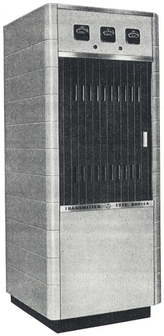
| GENERAL DESCRIPTION |
 FEATURES
| TECHNICAL SPECIFICATIONS | |
| Type of Emission | A 3 |
| Output Frequency Range | 3.9 to 26.1 mc/s |
| Rated Power Output at Transmitter Terminals | 1 kw, carrier |
| Output Load Impedance | 50 to 230 ohms unbalanced 300 to 600 ohms balanced Resistive ±JO.1R |
| Spurious Frequency Radiation | -40 db |
| Frequency Stability | 0.003% |
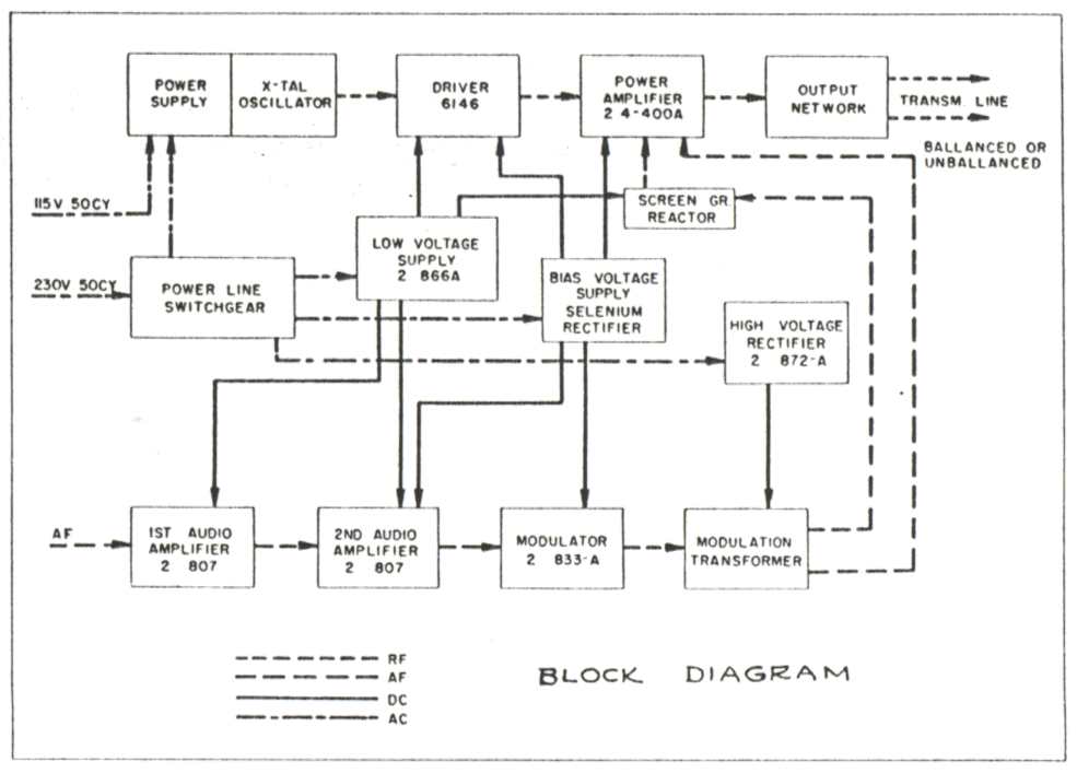
| Type of Modulation | High-level Class B |
| Program Input Impedance | 150/600 ohms |
| Program Input Level | +10 dbm ±2 dbm |
| Audio Frequency Response | ±2 db, 30 to 10,000 cps (1030 cps, 60% reference) |
| Modulation Capability | 400 cps:100% 50 to 7500 cps: 90% minimum |
| Envelope Distortion (1000 cps, 90% mod.) | 4% |
| Noise Level, Unweighted (below 100% mod.) | 52 db |
| Carrier Shift Up to 100% Modulation | Less than 5% |
| Power Consumption Unmodulated 40% Modulation 100% Modulation |
2900 watts, approx. 3100 watts, approx. 3900 watts, approx. |
| Power Factor | .9 |
| Power Line Requirements Transmitter Cabinet Lights |
230 volts, single-phase, 60 cy., available also for 50 cy. 115 volts, single-phase, 50/60 cy. |
| Permissible Power Line Variation | 5% |
| Ambient Temperature Range | +10°C to +45°C |
| Elevation | 8000 feet maximum |
| Transmitter Height | 84" |
| Transmitter Width | 33" |
| Transmitter Depth | 32 9/16" |
| Transmitter Floor Space | 7.5 sq. ft. |
| Transmitter Weight (Unpacked) | 1500 lbs. (approx.) |
| Specifications may change without notice | |
| TUBE COMPLEMENT | |||||
| RF stages | AF stages and modulator | Rectifiers | |||
| Number | Type | Number | Type | Number | Type |
| 2 | 4-400A | 2 | 833A | 2 | 8008 |
| 1 | 6146 | 4 | 807 | 2 | 866A |
| THIS TYPE OF TRANSMITTER IS INSTALLED IN THE FOLLOWING COUNTRIES | |||||
| ITU | Country | ITU | Country | ||