PHILIPS KV2 FL5/91

GENERAL DESCRIPTION


photo Philips KV2 FL5/91 
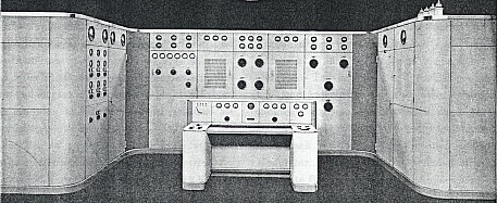
5 kW TROPICPROOF SHORTWAVE BROADCAST TRANSMITTER

The construction of the transmitter is based on the same principles which we first applied to design of the 10 kW broadcast transmitter KVFH 10/12 with a view to achieving the most practical and surveyabIe grouping of the transmitter stages and their elements, easy accessibility of all parts and a stylish outward appearance. The 10 kW transmitter in question is now being manufactured in series as a standard type and is in operation in numerous broadcast stations, mostly in the tropics.

The ground plan of the 5 kW equipment KV2 FL5/91 is likewise horseshoe-shaped, which allows of complete surveyability from the control desk set up in the middle. The transmitter stages, and also the mains switching and rectifier part, are separate units mounted in metal frames.

The lefthand part contains the devices for switching the installation on and off and also the power supply elements for the valve filaments. The central part comprises, from left to right, the 5 H.F. stages and the modulator. The righthand part contains the elements for feeding the anodes and the screen grids of the transmitting valves, as well as the smoothing condensers and the choke coil.

The individual parts as well as the general construction of the equipment are calculated to meet the heaviest demands of tropical climates.

For instance, the construction is specially damp resistant.

The PB 3/1000 is, for normal use, a so-called "radiation-cooled" valve. Yet we have introduced here forced-aircooling, because otherwise there is a risk of the ambient temperature becoming too high in the whole transmitter cabinet. It is for this reason as well that an additional fan is built into the rear of the transmitter for drawing out the hot air.

Output, modulation depth

The aerial power, measured at the beginning of the transmission line, amounts to 5 kW.

The maximum modulation depth is 100%.

Waverange

The transmitter is designed for operation on 2 fixed, crystal-controlled wavelengths between 40-131 m (7500-2290 kc/s). For quickest changeover from one wavelength to the other the tuning condensers of all the stages, excepting the oscillator stage, are provided with precision spring-catch devices ensuring greatest precision. The oscillator stage is provided in duplicate; consequently there is a special oscillator for each of the two fixed wavelengths. The time required for changing over from one wavelength to the other is not more than 2 minutes!

Crystal-control and self-oscillation

The oscillator stage can also function as a self-excited stage; changeover from crystal-control to self-excitation is effected by means of a switch.

Modulation

Modulation takes place in the suppressor grid circuits of the pentodes PB 3/1000 of the 4th HF stage. The modulator comprises 2 pentodes PE 06/40. In the control desk is the modulation preamplifier (line amplifier); this is connected to the modulator via a transformer. For greatest possible reduction of the non-linear distortion inverse feedback is provided. This rectifier contains 4 diodes EZ4.

Great constancy of the wavelength

For the crystal-controlled wavelenghts the tolerance of the carrier wave frequency is maximum ± 0.005% when the mains voltage fluctuates not more than ±5% and the ambient temperature not more than ±15° C.

High fidelity

Provided the voltage at the input of the line amplifier is maintained constant, the LF component of the rectified aerial current shows a maximum deviation from the zero level of ±1 dB within the frequency range of 30-10,000 c/s at a modulation depth of 90%.

Low non-linear distortion

For frequencies between 30-5000 c/s and a maximum modulation depth of 90% the non-linear distortion does not exceed 4%.

Low background-noise and hum

The modulation depth due to background noise and hum does not exceed 0.25%.

Required LF input voltage

For a modulation depth of 100% a voltage of 6 V is required at the input terminals of the line amplifier (input impedance 600 ohms) built into the control desk.

Explanation of the circuit diagram

The transmitter comprises the following stages:

  1. A twin, crystal-controlled oscillator stage, each stage with 2 valves CC2. For each oscillator a thermostat with 2 crystals is provided, one of which is kept in reserve. In order to prevent possible frequency variations when switching on, both oscillators remain switched on permanently.
  2. Separator stage with two pentodes PE 04/10. This stage functions entirely without grid current, so that no reaction on the oscillator stage can occur.
  3. First HF amplifier stage with 2 pentodes PE 1/80. This stage operates in class C adjustment.
  4. Second HF amplifier stage with 2 pentodes PB 3/1000. Modulation is effected in this stage, namely in the suppressor grid of the two valves.
  5. Power stage with 2 pentodes PAL 12/15. This stage operates as class B amplifier.
  6. Modulator with 2 parallel-connected pentodes PE 06/40. In the control desk is the modulation amplifier (line amplifier) with valves EB4, EBC3 and EL5.
Power supply

With the exception of the modulation and output stage all the filaments are AC fed. The high tensions are delivered by valve rectifiers. The primary power consumption amounts to 33 kW; the power factor is 1 when the condensers for improving the power factor are in circuit.

Cooling

All the valves are air-cooled. The valves in the last two HF stages function with forced air-cooling by means of fans.

Blocking system and safety devices

The equipment can only be operated when the necessary switching manipulations are carried out in a certain order of sequence. If this is not done the blocking system comes into operation. Consequently no harm to the equipment can occur when switching is effected in a careless manner. With a view to protecting the attendants against the danger of high tension all doors behind which there are live parts carrying a high tension are provided with automatic door contacts. Should one of these contacts be interrupted the high tension is cut out in the whole equipment.

Control desk

The control desk contains all the devices for supervising the modulation, such as a measuring instrument for the average modulation depth and a modulation limiter, with indicator, which limits the modulation to slightly under 100%. The desk also contains the two-stage modulation preamplifier (line amplifier) with amplifier valves EBC3 and EL5. In the desk are further housed a monitor amplifier which can be connected to different parts of the transmitter by means of press buttons. Regulation of the control grid voltages of the gasfilled rectifier valves for the anode feeding of the power stage, as well as adjustment of the anode voltage of the power stage, are likewise carried out at the control desk.

A press-button switch on the control desk enables to cut out the whole installation in case of emergency; by means of a further press button the 12 kV rectifier can be switched off instantly.

TUBE COMPLEMENT
RF stages AF stages and modulator Rectifiers
Number Type Number Type Number Type
2 PAL 12/15 2 PE 06/40 2 506
2 PB 3/1000 1 EB 4 11 DCG 4/1000
2 PE 1/80 3 EBC 3 6 DCG 5/2500
2 PE 04/10 1 EL 5 2 1561
4 CC 2 1 EL 3


8 EZ 4


2 1561


THIS TYPE OF TRANSMITTER IS INSTALLED IN THE FOLLOWING COUNTRIES

ITU Country
ITU Country