| TECHNICAL SPECIFICATIONS |
| Application |
Commercial continuous broadcast service |
| Power output (unmodulated carrier) |
1,000/500 W nominal |
| Frequency of operation |
one, within the band of 2.3 to 17.9 MHz |
| Mode of emission |
20A3 |
| Frequency control |
By quartz crystal mounted in thermostatically-controlled oven |
| Frequency tolerance |
± 0.003% |
| Output circuit |
600 ohms, balanced |
| Type of modulation |
High level, class B |
| AF input impedance |
600 ohms balanced |
| AF input level |
+ 10 dbm at 100% mod. (1,000 Hz) |
| Modulation capability |
100% (from 50 to 10,000 Hz) |
| Linear distortion |
Flat, within ± 1.5 dB from 50 to 10,000 Hz, reference 1,000 Hz |
| Non-linear distortion |
Less than 3% from 50 to 7,500 Hz, up to 90% modulation |
| Noise-level |
Better than -54 dB, unweighted, reference 1,000 Hz at 100% modulation |
| Power supply |
3 x 220 V, 50 or 60 Hz |
| Thermal oven supply |
110/220 V, monophase, 50/60 Hz |
| Power consumption |
1) Thermal oven: 24 VA
2) Transmitter, 100% mod.: 3.7 Kw (1,000 W output); 2.3 Kw (500 W output) |
| Power factor |
0.92 approx. |
| Ambient temperature |
From 0° to + 45°C, at sea level |
| Relative humidity |
Up to 95% |
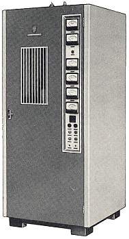
| Dimensions |
Height: 210 cm (82 in.)
Width: 90 cm (35 in.)
Depth: 88 cm (34 in.) |
| Weight, less tubes (unpacked) |
545 kg (1,200 lb.) |
 These transmitters have been specially designed and built to ensure the maximum of simplicity and economy of operation plus high stability and audio fidelity. They are fully tropicalized and suitable for continuous operation under severe climatic conditions.