HARRIS SW-100 B

GENERAL DESCRIPTION


SW-100 B, 100 kW Auto Tuning Short Wave Broadcast Transmitter

Harris SW-100 B . . . the latest in a line of legendary performers

photo Harris SW-100 B * Pulse Duration Modulator provides greater program sideband power for increased effective coverage.

* Reduced operating costs compared to other 100 kW designs from an overall AC efficiency of greater than 55%.

* Capable of 10 pre-set channels. Automatic tuning in 10 seconds or less minimizes programming disruptions.

* Vapor phase cooling provides constant tube anode temperature resulting in extended tube life.

* Spare inventory minimized with only three tube types used.

* Front and rear cabinet accessibility eases maintenance.

The Harris SW-100 B delivers overall performance superior to other 100 kW shortwave broadcast transmitter designs. The transmitter is high level plate modulated using Harris' patented highly efficient Pulse Duration Modulator (PDM). A 10-channel pre-set auto tuning system permits 10 second or less frequency changes anywhere from 3.2 to 22 MHz. These, in combination with a number of other outstanding features, make the SW-100 B the logical choice in 100 kW shortwave transmitters.

The Modulator System
Harris' patented Pulse Duration Modulator is characterized by low plate dissipation and low tube peak currents. Peak cathode currents are about one-half that of comparable transmitters. Average plate dissipation runs substantially below rated levels with all peak voltages being maintained well below component ratings.

Greater Sideband Power For Increased, Effective Coverage
The highly efficient Harris Pulse Duration Modulator is capable of high average modulation levels. Unlike other designs using modulator transformers and reactors, the Pulse Duration Modulator is DC coupled from the input stage to the final PA. This feature permits the use of trapezoidal, or clipped audio processing. This technique significantly increases the average sideband power, yielding increased effective coverage through improved received signal-to-noise. The SW-100 B transmitter has modulation power to make your signal stand out on the crowded shortwave bands.

Reduced Operating Costs
The Harris Pulse Duration Modulator employed in the SW-100 B is almost 90% efficient (instead of the usual 50% to 60%), enabling the transmitter to achieve an unusually high overall efficiency of greater than 55%. This represents lower installation costs on AC power equipment such as wiring, disconnects or even power generators. Substantial long term savings in power costs are gained over the operating life of the SW-100 B.

RF Section
Two frequency sources are available on the SW-100 B. The standard SW-100 B comes complete with up to 10 crystals operating in a precision temperature controlled oven. This FET crystal oscillator stage has a built-in AGC control which compensates for level differences associated with each of the in dividual crystals.

As an option, the SW-100 B can be configured with an external frequency synthesizer.

Solid state RF amplifiers amplify the RF signal to the 4CX1500A tetrode driver tube. Following the driver is the 4CV100,000E/P tetrode final. The 4CV100,000E/P has an excellent shortwave broadcast application track record, and will provide thousands of hours of dependable service.

The unbalanced output of the PA tank network is transformed using a balun into a balanced 300 output impedance. The SW-100 B can also be configured for a 50 ohm unbalanced output for use with coaxial transmission lines.

Several directional couplers are incorporated in the SW-100 B and monitor useful forward and reflective power levels in the output network and the actual antenna load connected to the SW-100 B. VSWR overload protection is also featured in the SW-100 B.

Convenient Power Control
The Pulse Duration Modulator used in the SW-100 B also provides convenient low level, front panel power control from zero to full 100 kW operation. There are no transformers to tap or PA loading controls to change. This feature is very handy should trouble occur in the feeder or antenna system, and continued operation is only feasible at reduced power.

Standard AC Power Line Control
The incoming AC power lines to the SW-100 B are controlled to insure uniform transmitter operation. The dependable SCR controller used on the HV power supply fulfills two important requirements; 1) smooth, high voltage ramp-up without the use of cumbersome step-start resistors, 2) maintenance of constant high voltage over moderate swings in incoming AC line voltage. The other SW-100 B AC service is regulated by a rugged auto adjusting transformer.

Only Four Tubes Used...To Minimize Spares Inventory and Cost
The SW-100 B employs just four tubes. Rugged ceramic 4CV100,000E/P power tetrodes are used in the power amplifier and modulator. The Pulse Duration Modulator driver stage is solid state, incorporating a high efficiency MOSFET amplifier. The RF driver consists of a rugged 4CX1500A, and the damper diode is a rugged long lasting 2CX10,000F. Use of only four tubes and three tube types greatly reduces spares stock and the associated costs.

10-Channel Pre-Set Tuning
Few controls and ample metering make the SW-100 B the easiest tuning high power transmitter available. Up to ten different frequencies from 3.2 to 22 MHz can be remembered, which allows pushbutton re-tuning to any pre-set frequency.

The Servo System
The all solid-state servo system will automatically tune any of 10 pre-set channels in about 10 seconds. Each channel is "remembered" on one plug-in card. Auxiliary channel switching also is provided. The fast tuning time is made possible because the HV supply is not disabled during the tune cycle; the RF drive is turned off in a low level solid-state stage, and all tuning is done in parallel. When the tuning has been accomplished, the PDM modulator is turned back on silently and smoothly.

Protective Circuits
All major components of the SW-100 B are protected by circuit breakers. Tubes and transistors are guarded by overload relays or current-limiting devices.

A quick-acting circuit protects against damage by high voltage arcs by limiting the energy in such arcs to less than 10 watt/seconds. Protection against voltage standing wave ratios of greater than 2.0 to 1.0 is provided. Both forward and reflected power are metered at the front panel.

In case of momentary RF overloads, the SW-100 B will recycle three times automatically. Should a third overload occur within a thirty second period, the transmitter will remain off until manually reset. However, if the time between overloads is greater than thirty seconds, continuous recycling will occur.

The SW-100 B employs a unique method of transmitter protection. The modulator tube may be turned off in a low level state in about five microseconds. This removes the HV from the PA tube, thus eliminating most faults which normally occur. The HV supply (diodes and transformer) is capable of withstanding repeated short circuits without harming the unit.

An automatic RF drive control monitors the PA screen current to insure safe operating levels are maintained under a wide range of tuning conditions.

Additional protection is provided by HV primary and secondary overload circuits. Tubes and transistors are also protected by current limiting impedances.

Designed For Wide Range Of Climates
The SW-100 B transmitter will give top performance in a wide range of climates from hot and humid, to dry and dusty. All transformers and similar components are hermetically sealed, encased, or vacuum impregnated.

Minimum Floor Space
Due to the elimination of large iron core components such as the modulation transformer and modulation reactor, the SW-100 B requires only seven square meters (78 square feet) of floor space. Advanced cabinet design provides easy accessibility to all components.

Transmitter Layout
The standard SW-100 B consists of two cabinets, a remote heat exchanger and an external high voltage power transformer and voltage regulator.

TECHNICAL SPECIFICATIONS
Power Output 100,000 watts nominal unmodulated
RF Frequency Range 3.2 to 22.0 MHz
Method of Tuning Manual, or selection of 10 pre-set channels
RF Output Impedance 300 ohms balanced, 2.0 to 1 maximum VSWR
RF Frequency Stability ±1 x 10⁻⁶ (±22 Hz at 22 MHz)
Spurious and Harmonic Emission Less than 50 mW
Carrier Shift Less than 2% at 95% modulation at 1000 Hz
Audio Frequency Response ±1.5 dB from 50 to 10,000 Hz referenced to 1,000 Hz at 95% modulation
Audio Harmonic Distortion 3% or less from 50 to 10,000 Hz at 95% modulation
Noise 55 dB below 400 Hz, 100% modulated level
Audio Input Level 0 dBm ±2 dB for 100% modulation
Audio Input Impedance 600/150 ohms, balanced or unbalanced
Modulation Level 100% sinusoidal, 60 minutes, 500-5000 Hz
Trapezoidal Modulation Less than 5% tilt or overshoot, 100 Hz to 2000 Hz measured using 12 dB clipped sine wave
Power Input Any specified voltage 380V to 480V, 3 phase, 50 or 60 Hz. Phase unbalance 5%, Regulation 5%
Power Consumption No Modulation: 180 kW
30% Modulation: 190 kW
100% Modulation: 250 kW
Power Factor Greater than 95%
AC Line Voltage Control Electronic primary voltage control for all power supplies
Overall Efficiency 55% @ average modulation
Temperature Range 0 to +50°C ambient air temperature
Humidity 95% relative humidity, maximum
Storage Temperature -35°C to +60°C
Altitude Up to 1829 meters (6000 feet) above sea level
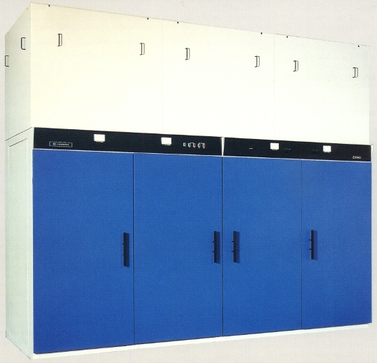
Cabinet Data The two main cabinets measure 366 cm (12 feet) wide, 137 cm (4.5 feet) deep,
and 304 cm (10 feet) high, plus external components
Specifications may change without notice

TUBE COMPLEMENT
RF stages AF stages and modulator
Number Type Number Type
1 4CV100,000E 1 4CV100,000E
1 4CX1500A 1 2CX10,000F


THIS TYPE OF TRANSMITTER IS INSTALLED IN THE FOLLOWING COUNTRIES

ITU Country
ITU Country
flag SEY SEY SEYCHELLES flag SDN SDN SUDAN
flag USA USA USA