GATES HF-100 C

GENERAL DESCRIPTION


100,000 WATT HIGH FREQUENCY BROADCAST TRANSMITTER

Model HF-100 C


photo Gates HF-100C 
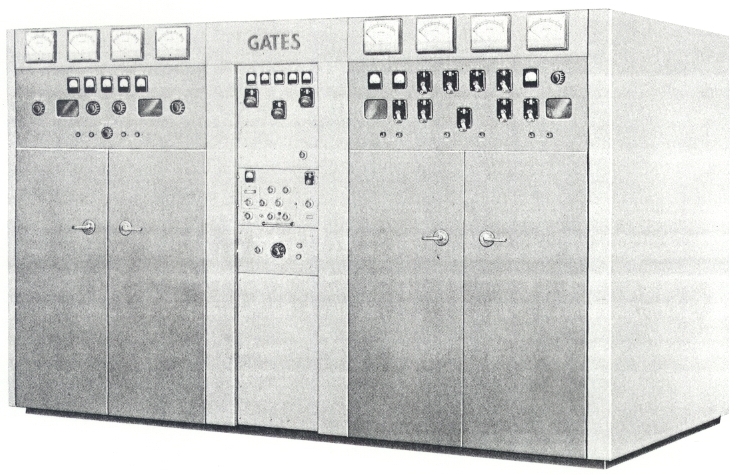
Designed to operate in world wide climates under the rigorous demands of continuous duty, the new HF-100 C possesses compact size, rapid frequency change, interchangeability of PA and modulator tubes, less tube types, longer tube life, and low power consumption.

CONSTRUCTION: The HF-100 C consists of three main cubicles that are accessible from front and rear: audio driver and modulators, RF exciter-driver control cubicle and PA cubicle.

RADIO FREQUENCY SECTION: The RF exciter-driver is the center cubicle and is rated at 85 watts output. Exciter has a crystal selection system wih 10 positions selectable from the front panel. 6 KW driver is conservatively rated with plenty of reserve power.

POWER AMPLIFIER SYSTEM: Power amplifier uses two Federal 6804 forced air cooled tubes in push-pull.

AUDIO SYSTEM: All audio stages are located in the modulator cubicle. The 1st audio stage uses two 6146 tubes push-pull. The 2nd audio stage uses two 813 tubes operating as a push-pull amplifier. The audio driver stage uses 5736 triodes operating in a direct coupled cathode follower circuit. Adjustment of bias resistors, feedback and carrier hum are simple. Over-all feedback is approximately 15 db an optimum value for minimum distortion and noise.

MODULATION: Type F6804 tubes used in the power amplifier are also used as modulators. High level plate modulation is used in the HF-100 C transmitter, which provides for a constantly available reserve audio-power. The HF-100 C modulator is designed for continuous duty at extremely high levels of average modulation.

POWER SUPPLIES: All power supplies in the HF-100 C transmitter utilize silicon rectifiers. This includes the main high voltage rectifiers which provide approxmately 15 KV plate for the modulator tubes and approximately 12.5 KV on the final RF amplifier. Separate high voltage plate transformers for modulator and RF amplifier are used.

BAND SWITCHING: A new concept of plate tank circuit design makes necessary a minimum of adjustments other than from the front panel, to provide for continuous coverage over the range of 4-30 MCS. No plug-in coils are used in the HF-100 C transmitter and frequency change can be accomplished in less than five minutes.

CONTROL: The HF-100 C is provided with a generous supply of overload and under-voltage relays. Every circuit large or small is protected most adequately.

TECHNICAL SPECIFICATIONS
Power Output 100,000 watts
Output Impedance 300-800 ohms
RF Range 4-30 MC
Frequency Stability .003% or better
RF Harmonics Meets or exceeds FCC requirements
Audio Frequency Response 85% modulation (50-10,000 cycles) ±1.5 db
Audio Harmonic Distortion (0-95% modulation from 50 to 7500 cycles) 4% or less
Audio Input 100% modulation sine wave, 400 cps +10 dbm
Audio Input Impedance 600 ohms
Primary Voltage 460 volt ±5%, 3 phase, 50 or 60 cycles as specified
Power Consumption Carrier 15 KW
Average Program 173 KW
100% Modulation 255 KW
Carrier Shift (100% modulation with 400 cps) 5% or less
Total Number of Tubes 22
Total Tube Types 13
Size 6.5 ft. high, 14 ft. wide, 5 ft. deep with external blower
Cubage 1555
Specifications may change without notice

TUBE COMPLEMENT
RF stages AF stages and modulator Rectifiers
Number Type Number Type Number Type
2 F-6804 2 F-6804 2 5R4GYA
2 6076 2 WL5736 1 6AL5
2 6146 2 813

2 5763 2 6146

1 OB2


1 6AQ5


THIS TYPE OF TRANSMITTER IS INSTALLED IN THE FOLLOWING COUNTRIES

ITU Country
ITU Country