| GENERAL DESCRIPTION |
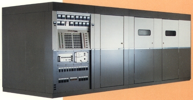 Features
| TECHNICAL SPECIFICATIONS | |
| Carrier Output | 250,000 watts, minimum |
| PEP Output (SSB optional mode) | 500,000 watts, minimum |
| Modulation | Pulse-width modulator (PWM) |
| Emission | A3E or A3J (USB) |
| Frequency Range | International broadcast bands, 10 preset channels 3.9 to 22 MHz |
| Frequency Control | Frequency synthesizer |
| Frequency stability | 1x10⁻⁸ per day, optional greater stability available on special order |
| AF Input Impedance | 600 Ohms, 30 dB return loss |
| AF Input Level for 100% | Sinewave modulation +10 dBM ±2 dB continuously adjustable, other levels optional |
| AF Response | ±1 dB 50 to 4,500 Hz ±2 dB 4,500 to 6,000 Hz Referred to 1,000 Hz at any modulation level |
| AF Distortion | Less than 3% THD, 50 to 4,500 Hz at any modulation level up to 100% positive and negative |
| SSB Option | |
| SSB Carrier Suppression | -6 or -12 dB selectable |
| SSB Unwanted Sideband Suppression | -55 dB |
| SSB Odd Order IM Products | -30 dB (two tone test) |
| Carrier Shift | 1.5% or less including power line variations of up to 2% |
| Modulation Capability | 100% positive and negative modulation continuously by program, band limited noise or sinewave modulation 50 to 6,000 Hz at any power level up to 250 kW |
| Controlled Carrier Modulation | 0 to 6 dB carrier reduction in 1 dB increments |
| Overmodulation | Adjustable peak clipping may be set to desired maximum modulation level. Transmitter will accept input level of 10 dB over 100% without damaging equipment. AF input exceeding 10 dB over 100% modulation level may cause protective overload circuits to operate. |
| Residual Carrier Noise | 55 dB unweighted below 100% modulation at 1,000 Hz measured in a bandwidth of 10 to 15,000 Hz |
| RF Harmonic and Spurious Output Level | Less than 2.5 milliwatts up to a maximum frequency of 900 MHz |
| Output Impedance | 75 Ohm unbalanced - standard 300 Ohm balanced - optional Maximum allowable VSWR 1.8:1.0 at full power |
| Power Source | 4160 volts, three phase, three wire, 50/60 Hz (others optional on special order) |
| Power Factor | Better than 0.95 |
| Power Consumption | Maximum input power 568 kW at 100% sinewave modulation |
| Efficiency | 65 to 70% at 250 kW carrier power output, depending on the ambient temperature and operating frequency; typically 66% at any modulation depth |
| Maximum Operating Conditions | Altitude - 2,000 feet (600 meters) Ambient temperature - 10 to 45°C Relative humidity - 95% |
| Dimensions: Main cabinet group | 7' (2.13 m) H 22' (6.71 m) W 6' (1.83 m) D |
| Dimensions: Modulator group | 7' (2.13 m) H 12' (3.66 m) W 6' (1.83 m) D |
| Dimensions: Power supply vault (dependent on building layout) |
8' (2.44 m) H 21' (3.66 m) W 14' (4.27 m) D |
| Weight and volume (packed for export) | 38,000 lbs (17,100 kg) 2,800 cubic ft. (79.29 cubic meters) |
| Specifications may change without notice | |
| TUBE COMPLEMENT | |||
| RF stages | AF stages and modulator | ||
| Number | Type | Number | Type |
| 1 | 4CV250,000C | ||
| 1 | 3CW20,000A7 | ||
| THIS TYPE OF TRANSMITTER IS INSTALLED IN THE FOLLOWING COUNTRIES | |||||
| ITU | Country | ITU | Country | ||
| POR | PORTUGAL | ||||