| GENERAL DESCRIPTION |
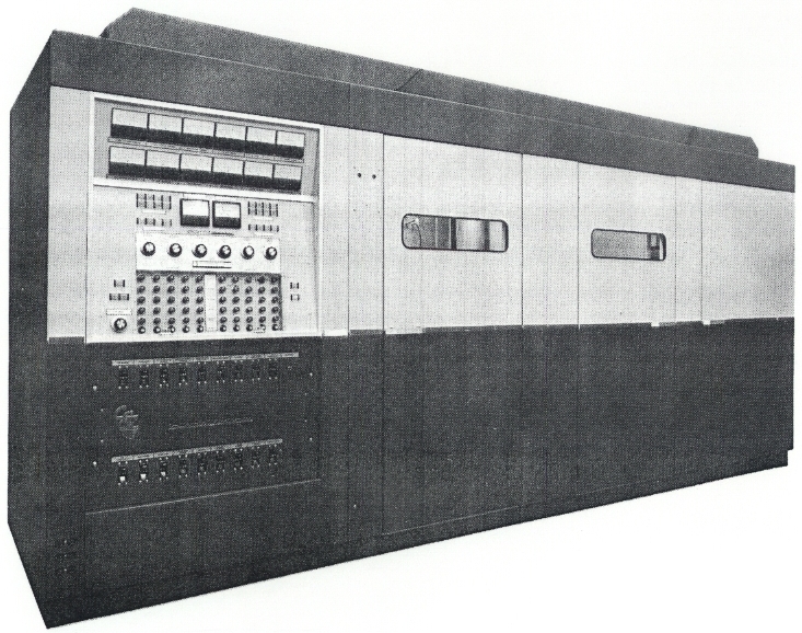 Continental Electronics' vast knowledge and background in the design, development, manufacture, system plans, installation, and operation of high-power and super-power transmitters have been fully utilized in the design of our Type 417D Transmitter.
| TECHNICAL SPECIFICATIONS | |
| Carrier Output Power | 50 kilowatts |
| Types of Emission | Amplitude Modulation (A3) and Frequency Shift (F1) |
| Types of Modulation | High-level plate, Class "AB" modulator |
| Final Power Amplifier | Class "C" operation |
| Frequency Range | 3.2 to 22 MHz |
| Output Impedance | 75 ohms unbalanced or 300 ohms balanced (optional). VSWR less than 1.5:1 |
| Modulation Capability | 100%, 50 to 10,000 Hz sinusoidal |
| Radio Frequency Harmonics and Spurious Radiation | Less than 50 mW (Complies with CCCIR Recommendations) |
| Audio Input Impedance | 600/150 ohms, balanced or unbalanced |
| Audio Input Levels for 100% Modulation | +10 dBm at 1000 Hz |
| Audio Frequency Response | ±1 dB from 50 - 7500 Hz @ 90% Modulation |
| Audio Frequency Distortion | Less than 3% RMS, 50 - 7500 Hz @ 90% Modulation |
| Residual Carrier Noise | More than 55 dB (unweighted) below 100% modulation level at 1000 Hz |
| Carrier Shift | Less than 3% at 100% Modulation exclusive of power line variations |
| Relative Humidity | 95 Percent |
| Altitude | 6000 feet above sea level |
| Power Consumption | Unmodulated, 98 kW Sinusoidal: 30% Modulation, 114 kW 50% Modulation, 125 kW 100% Modulation, 135 kW |
| Primary Power Requirements | 360 to 480 volt, (±5% regulation), three-phase, 50/60 Hz (other on special order) |
| Power Factor | Better than 0.9 |
| Ambient Temperature Range | +5°C to +45°C |
| Specifications may change without notice | |
| TUBE COMPLEMENT | |||
| RF stages | AF stages and modulator | ||
| Number | Type | Number | Type |
| 1 | 4CX35,000C | 2 | 4CX15,000A |
| 1 | 4CX3000A | ||
| THIS TYPE OF TRANSMITTER IS INSTALLED IN THE FOLLOWING COUNTRIES | |||||
| ITU | Country | ITU | Country | ||
| EGY | EGYPT | KOR | KOREA SOUTH | ||