| GENERAL DESCRIPTION |
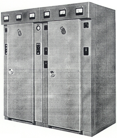 Designed for operation in the International short wave broadcast band, the Type 416C utilizes Continental's field-proven screen modulation system which makes possible an excellent degree of performance. Transmitter is manually tuned over the frequency range from 3 to 22 megacycles. Excitation is provided by either a crystal oscillator or a variable frequency oscillator. The Type 416C is housed in frameless aluminium cabinets which provide excellent shielding, light weight and easy access to all components.
| TECHNICAL SPECIFICATIONS | |
| Audio Input Impedance | 150/600 ohms |
| Audio Input Level (100% modulation) | +10 ±2 dbm |
| Audio Frequency Response (95% modulation) 50-7500 cps 30-10,000 cps |
±1 db ±1.5 db |
| Audio Distortion (95% modulation) 50-10,000 cps | 3% |
| Noise (Below 100% modulation) | -60 db |
| Carrier Shift (95% modulation) | less than 2% |
| Type of Modulation | high-level screen grid |
| Frequency Range | 3-22 mc |
| Type of Emission | A3 |
| Type of Output | unbalanced coaxial |
| Output Impedance | 50 ohms |
| Output Capability | 10,600 watts |
| Maximum Ambient Operating Temperature | +45° C |
| Power Source Required: Voltage Frequency |
208/230 volts, 3 phase 50-60 cps |
| Power Consumption | 30 kw (approx.) |
| Power Factor | 90% |
| Permissible Combined Voltage Variation and Regulation | ±5% |
| Mechanical: Height Width Depth Floor Space Weight (unpacked) Building Entrance Requirements |
78 inches 72 inches 41 inches 18 sq. ft. 2300 lbs. 36 inches wide by 41 inches high |
| Specifications may change without notice | |
| TUBE COMPLEMENT | |||
| RF stages | AF stages and modulator | ||
| Number | Type | Number | Type |
| 2 | 4CX10,000D | ||
| 1 | 4CX300A | ||
| THIS TYPE OF TRANSMITTER IS INSTALLED IN THE FOLLOWING COUNTRIES | |||||
| ITU | Country | ITU | Country | ||