| GENERAL DESCRIPTION |
 PURPOSE
| TECHNICAL SPECIFICATIONS | |
| Total Cubical Contents | 212.2 Cu. Ft. (Uncrated) |
| Total Weight | 4842 lbs (Uncrated) |
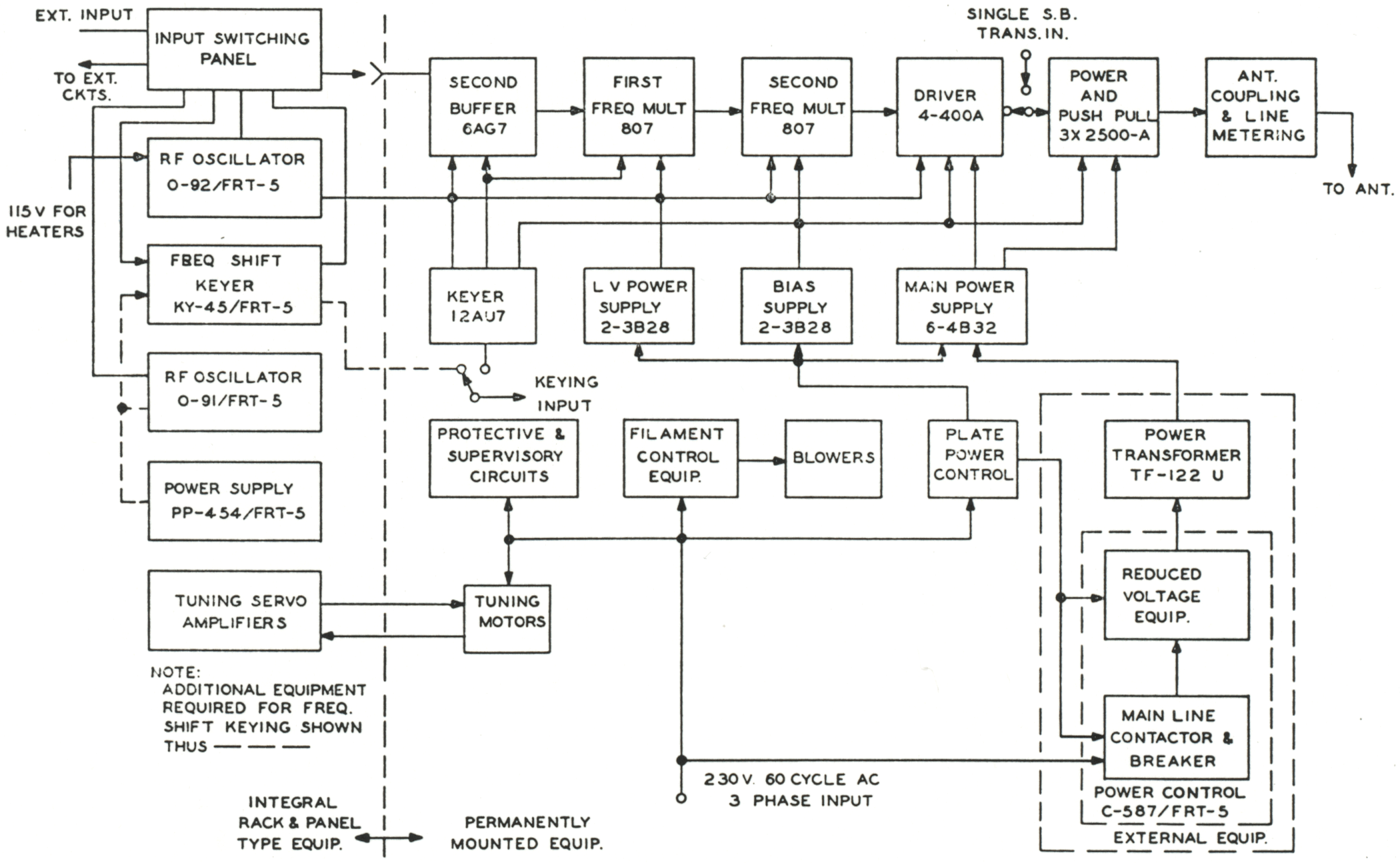
| Frequency Range | 4,000 to 26,000 kilocycles |
| Frequency Multiplier Range | 4 to 26 megacycles |
| First Frequency Multiplier | 4 to 13 megacycles |
| Second Frequency Multiplier | 4 to 26 megacycles |
| Type of Frequency Control | Crystal or Stabilized Oscillator |
| Type of Emission | a. A-1 (carrier ON-OFF) b. Frequency shift |
| Keying Speed | Up to 400 wpm |
| Nominal Carrier Output For Each Type of Emmission | 15 kilowatts for A-1 emission, into a fixed 600 ohm load 15 kilowatts for frequency shift emission into fixed 600 ohm load |
| Power Factor of Equipment | a. Starting (Filaments ON): 94% b. Standby (High Voltage ON, Key Open): 90% c. Normal Operation: 94.5% |
| Power Source Requirement | a. Voltage: 207 to 253 volts; designed for a center voltage of 230 volts b. Frequency: 60 cps ±5% c. Number of phases: 3 phase d. Input Power: Key down: 27.5 KW; Key Up: 4.25 KW |
| Crystal | Type AN/CR27-U with fundamental frequency between 2.0 and 4.2 mc required |
| TUBE COMPLEMENT | |||||
| RF stages | AF stages and modulator | Rectifiers | |||
| Number | Type | Number | Type | Number | Type |
| 2 | 3X2500A3 | 6 | 4B32 | ||
| 1 | 4-400A | 4 | 3B28 | ||
| 2 | 807 | ||||
| 1 | 6AG7 | ||||
| THIS TYPE OF TRANSMITTER IS INSTALLED IN THE FOLLOWING COUNTRIES | |||||
| ITU | Country | ITU | Country | ||
| MRC | MOROCCO | PHL | PHILIPPINES | ||
| USA | USA | ||||