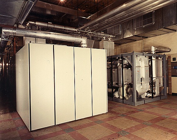
| GENERAL DESCRIPTION |
| TECHNICAL SPECIFICATIONS | |
| PHYSICAL SPECIFICATIONS | |
| Size (width x depth x height) | RF Unit: 8 x 17 x 7 feet AF Unit: 7 x 3 feet 6 inches x 7 feet HVP Unit: 16 feet 3 inches x 34 feet x 8 feet 7 inches SCU: 16 x 11 x 9 feet |
| Total Weight | 68,500 pounds |
| Required Floor Space | RF Unit: 136 square feet AF Unit: 24.5 square feet HVP Unit: 553 square feet SCU: 176 square feet Total: 892 square feet |
| ENVIRONMENTAL SPECIFICATIONS | |
| Ambient Operating Temperature Range | Indoors: +1° to +50°C (+33.8° to +122°F) at sea level; +1° to +30°C (+33.8° to +86°F) at 10,000 feet above msl, linearly derated from sea level to 10,000 feet Outdoors: -35° to +50°C (-31° to +122°F) at sea level; -30° to +30°C (-22° to +86°F) at 10,000 feet above msl, linearly derated from sea level to 10,000 feet |
| Ambient Nonoperating Temperature Range | Indoors: +1° to +50°C (+33.8° to +122°F) at sea level; +1° to +30°C (+33.8° to +86°F) at 10,000 feet above msl, linearly derated from sea level to 10,000 feet Outdoors: -30° to +50°C (-22° to +122°F) at sea level; -30° to +30°C (-22° to +86°F) at 10,000 feet above msl, linearly derated from sea level to 10,000 feet |
| Ambient Storage Temperature Range (Equipment dry with no water in the cooling system) | -35° to +60°C (-31° to +140°F) |
| Ambient Relative Humidity Range | 0 to 95° |
| Altitude | 0 to 6,000 feet above msl, with 250-kw output power 6,000 to 10,000 feet above msl, 200-kw output power (Power is reduced by reducing the plate voltage) |
| ELECTRICAL SPECIFICATIONS | |
| Frequency Range | 3.95 to 26.5 MHz in 100 Hz increments |
| Frequency Stability | Same as exciter |
| Tuning Time | 12 seconds, maximum |
| RF Input | 100 mw to 400 mw, 50 ohms |
| RF Output | 250 kw into 75 ohms, unbalanced, or 300 ohms, balanced, with vswr of 2:1 maximum |
| Harmonics | At least 80 db below carrier |
| Carrier Shift | Less than 5% exclusive of power source regulation |
| Hum and Noise | At least 55 db below 100% modulation |
| Type of Modulation | High-level AM, FSK, or AM/FSK multiplex |
| Modulation Capability | Capable of 100% sine wave or clipped sine wave with less than 5% overshoot or droop on the flat top of a 100-hertz sine wave clipped 9 db |
| Modulation Duty Factor | Continuous at 100% sine wave; 5 minutes on and 15 minutes off at 100% clipped sine wave |
| Audio Input for 100% Modulation | -2 to +12 dbm, 600/150 ohm, balanced or unbalanced |
| Audio Response | Within 1 db from the 1000 Hz reference between 100 and 7500 Hz and within 2 db between 50 to 10,000 Hz, at all modulation levels up to 95% |
| Audio Distortion | Not more than 4% from 100 to 5,000 Hz, not more than 5% from 50 to 7,500 Hz |
| POWER INPUT SPECIFICATIONS | |
| Primary Power | 3-phase, 4160 volts to 13.8 kv, 50 or 60 Hz, 662-kw. No break, -48 volt dc., 7 amp (battery preferred) |
| Auxiliary Power | Single phase, 120 or 240 volts, 50 or 60 Hz, 15 amp |
| Power Consumption | Standby: 41-kw Carrier: 452-kw 95% sine-wave modulation: 662-kw |
| TUBE COMPLEMENT | |||||
| RF stages | AF stages and modulator | Rectifiers | |||
| Number | Type | Number | Type | Number | Type |
| 2 | 4CV100,000C | 2 | 4CV100,000C | ||
| 1 | 4CX3000A | 2 | 4CX350A | ||
| 2 | 4CX350A | 5 | 2N3568 | ||
| THIS TYPE OF TRANSMITTER IS INSTALLED IN THE FOLLOWING COUNTRIES | |||||
| ITU | Country | ITU | Country | ||
| AUS | AUSTRALIA | CAN | CANADA | ||